75-068628-16S Amphenol, 75-068628-16S Datasheet - Page 258
75-068628-16S
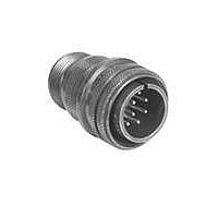
Manufacturer Part Number
75-068628-16S
Description
ER 20C 20#16 SKT PLUG
Manufacturer
Amphenol
Series
97 Seriesr
Datasheet
1.M3902932-260.pdf
(436 pages)
Specifications of 75-068628-16S
Mil Type
MIL-DTL-5015
Product Type
Connectors
Contact Style
Socket (Female)
Shell Style
Plug
Shell Size
28
Number Of Contacts
1
Insert Arrangement
28-16
Mounting Style
Panel
Termination Style
Crimp
Contact Type
Socket
Shell Plating
Chromate over Cadmium, Olive Drab
Contact Plating
Silver
Current Rating
23 A
Voltage Rating
4200 V
Body Material
Aluminum
Mounting Angle
Straight
Lead Free Status / Rohs Status
Lead free / RoHS Compliant


38999, Series III with PCB Contacts
TVP00R Wall Mounting Receptacle
(Back Panel Mounting) (With Clinch Nuts)
All dimensions for reference only.
*Consult Amphenol for more information on ordering connectors with clinch nuts.
Composite Series III connectors with PBC Contacts are available; consult Amphenol, Sidney, NY.
Z dimension is determined by contact type in the insert arrangement.
Most common options are shown; other options are available.
HOW TO ORDER
1.
2.
3.
Shell
Size
PART #
See chart below
628
11
13
15
17
19
21
23
25
88
91
9
Select a Shell Finish:
Base Number:
Select a Coded Shell Size:
See chart below
Example: 741= Size 9 Shell
88/91-628741-XXX
Designates olive drab cadmium plated
connector shell
Designates electroless nickel plated
connector shell
Base Number
Part Number
Clinch Nuts*
2 PLACES
2 PLACES
with
S
R
742-XXX
743-XXX
744-XXX
745-XXX
746-XXX
747-XXX
748-XXX
749-XXX
741-749,
88/91
Finish
Shell
1.
Number
0.1P-0.3L-TS
Contact Amphenol Aerospace for more information at 800-678-0141 • www.amphenol-aerospace.com
designates size 9-25 shell size.
Base
628
B Thread
Class 2A
(Plated)
2.
1.0000
1.1875
1.2500
1.3750
1.5000
1.6250
.6250
.7500
.8750
THREAD
CLINCH NUT
T
Shell Size
.005
Coded
741
3.
M
Max.
.469
.469
.469
.469
.469
.469
.500
.500
.500
L
Arrangement
Insert
- 35
THREAD
4.
+.000
–.005
.820
.820
.820
.820
.820
.820
.790
.790
.790
M
B
Contact Type/Alt.
Keying Positions
1.062
1.156
1.250
1.375
1.500
.719
.812
.906
.969
R
5.
P
RED
BAND
BLUE
BAND
4.
5.
1.094
1.187
1.281
1.344
1.437
1.531
1.625
1.750
1.875
Max.
S
Select an Insert Arrangement:
Refer to insert availability chart on page 239 and pin-out
illustrations on pages 241-255. In the chart the first number represents the
Shell size and the second number is the insert Arrangement.
Contact Type/Alternate Keying Positions:
Refer to page 240 for alternate rotation letters to use.
1.240 MAX.
AA
LL
M
-35
P
S
.112-40UNC-3B M12X1-6g
.112-40UNC-3B M15X1-6g
.112-40UNC-3B M18X1-6g
.112-40UNC-3B M22X1-6g
.112-40UNC-3B M25X1-6g
.112-40UNC-3B M28X1-6g
.112-40UNC-3B M31X1-6g
.138-32UNC-3B M34X1-6g
.138-32UNC-3B M37X1-6g
Designates Insert Arrangement Number
Designates Pin Contacts in Normal Position
Designates Socket Contacts in Normal Position
Thread
T
L
Thread
Metric
CONNECTOR WITH CLINCH NUTS
(4 PLACES)
V
Z
PCB TAIL STICKOUT
Amphenol
V THREAD
.062 .001 DIA.
†† Blue band indicates rear release contact
FOR SIZE 16 CONTACTS
.019
FOR SIZE 20 & 22D CONTACTS
Thickness
†Red band indicates fully mated
Designates true position dimensioning
retention system
Panel
Max.
.234
.234
.234
.234
.234
.234
.204
.204
.204
AA
.001 DIA.
+.006
–.000
.905
.905
.905
.905
.905
.905
.905
.905
.905
Aerospace
LL
.228–.178 .242–.181
.228–.178 .242–.181
.228–.178 .242–.181
.228–.178 .242–.181
.228–.178 .242–.181
.228–.178 .242–.181
.228–.178 .242–.181
.228–.178 .242–.181
.228–.178 .242–.181
Series III TV
Contacts
16 & 20
Size
Z
Contacts
Size 22D
257
Related parts for 75-068628-16S
Image
Part Number
Description
Manufacturer
Datasheet
Request
R

Part Number:
Description:
CBL BNC ST PLUG-PLG BEL 8218 36"
Manufacturer:
Amphenol Connex
Datasheet:
Part Number:
Description:
CBL BNC ST PLUG-PLG BEL 8218 24"
Manufacturer:
Amphenol Connex
Datasheet:
Part Number:
Description:
CBL BNC ST PLUG-PLG BEL 8218 12"
Manufacturer:
Amphenol Connex
Datasheet:
Part Number:
Description:
CBL BNC ST PLUG-PLUG BEL 8218 6"
Manufacturer:
Amphenol Connex
Datasheet:

Part Number:
Description:
CBL BNC ST PLUG-PLG BEL 8218 48"
Manufacturer:
Amphenol Connex
Datasheet:


Part Number:
Description:
Cable Specification: PU CABLE, UL20549 24AWG*8C+AD,OD= 6.0mm
Manufacturer:
Amphenol