MKT1813-410/015 Vishay, MKT1813-410/015 Datasheet - Page 10
MKT1813-410/015
Manufacturer Part Number
MKT1813-410/015
Description
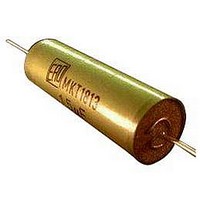
CAPACITOR POLYESTER FILM 0.1UF 100V AXIAL
Manufacturer
Vishay
Datasheet
1.MKT1813322255.pdf
(13 pages)
Specifications of MKT1813-410/015
Capacitor Dielectric Type
Polyester
Capacitance Tolerance
± 10%
Voltage Rating
100VDC
Capacitor Case Style
Radial Leaded
No. Of Pins
2
Capacitor Mounting
Through Hole
Capacitance
0.1µF
Lead Free Status / RoHS Status
Lead free / RoHS Compliant


MKT 1813
Vishay Roederstein
INSPECTION REQUIREMENTS
General Notes:
Sub-clause numbers of tests and performance requirements refer to the “Sectional Specification, Publication IEC 60384-2 and
Specific Reference Data”.
Group C Inspection Requirements
www.vishay.com
26
SUB-CLAUSE NUMBER AND TEST
SUB-GROUP C1A PART OF SAMPLE
OF SUB-GROUP C1
4.1
4.3.1
4.3
4.4
4.14
4.4.2
SUB-GROUP C1B PART OF SAMPLE
OF SUB-GROUP C1
4.6.1
4.6
4.7
4.7.2
Dimensions (detail)
Initial measurements
Robustness of terminations
Resistance to soldering heat
Component solvent resistance
Final measurements
Initial measurements
Rapid change of temperature
Vibration
Final inspection
For technical questions, contact: dc-film@vishay.com
CONDITIONS
Capacitance
Tangent of loss angle:
Tensile: Load 10 N; 10 s
Bending: Load 5 N; 4 x 90°
Method: 1A
Isopropylalcohol at room temperature
Method: 2
Visual examination
Capacitance
Tangent of loss angle
Capacitance
Tangent of loss angle:
θA = - 55 °C
θB = + 100 °C
5 cycles
Duration t = 30 min
Visual examination
Mounting:
See section “Mounting” of this specification
Procedure B4
Visual examination
For C ≤ 470 nF at 100 kHz or
for C > 470 nF at 10 kHz
Solder bath: 280 °C ± 5 °C
Duration: 10 s
Immersion time: 5 ± 0.5 min
Recovery time: Min. 1 h, max. 2 h
For C ≤ 470 nF at 100 kHz or
for C > 470 nF at 10 kHz
Frequency range: 10 Hz to 55 Hz
Amplitude: 0.75 mm or
Acceleration 98 m/s²
(whichever is less severe)
Total duration 6 h
DC Film Capacitor
MKT Axial Type
PERFORMANCE REQUIREMENTS
As specified in Chapters “General data” of
this specification
No visible damage
No visible damage
Legible marking
|ΔC/C| ≤ 2 % of the value measured initially
Increase of tan δ
Compared to values measured in 4.3.1
No visible damage
No visible damage
≤ 0.005 for:
C ≤ 100 nF or
≤ 0.010 for:
100 nF < C ≤ 220 nF or
≤ 0.015 for:
220 nF < C ≤ 470 nF and
≤ 0.003 for:
C > 470 nF
Document Number: 26013
Revision: 08-Dec-08
Related parts for MKT1813-410/015
Image
Part Number
Description
Manufacturer
Datasheet
Request
R

Part Number:
Description:
CAPACITOR POLYESTER 0.01UF, 400V, AXIAL
Manufacturer:
Vishay
Datasheet:
Part Number:
Description:
CAPACITOR POLYESTER 0.022UF, 250V, AXIAL
Manufacturer:
Vishay
Datasheet:
Part Number:
Description:
CAPACITOR POLYESTER FILM 0.1UF 250V AXIAL
Manufacturer:
Vishay
Datasheet:
Part Number:
Description:
CAPACITOR POLYESTER FILM 0.1UF 100V AXIAL
Manufacturer:
Vishay
Datasheet:
Part Number:
Description:
CAPACITOR POLYESTER FILM 0.1UF 250V AXIAL
Manufacturer:
Vishay
Datasheet:
Part Number:
Description:
CAPACITOR POLYESTER 0.22UF, 100V, AXIAL
Manufacturer:
Vishay
Datasheet:
Part Number:
Description:
CAPACITOR POLYESTER FILM 0.47UF 63V AXIAL
Manufacturer:
Vishay
Datasheet:
Part Number:
Description:
CAPACITOR POLYESTER FILM 1UF, 100V, AXIAL
Manufacturer:
Vishay
Datasheet:
Part Number:
Description:
CAPACITOR POLYESTER FILM 2.2UF 63V AXIAL
Manufacturer:
Vishay
Datasheet:
Part Number:
Description:
CAPACITOR POLYESTER FILM 3.3UF 63V AXIAL
Manufacturer:
Vishay
Datasheet:

Part Number:
Description:
357-036-542-201 CARDEDGE 36POS DL .156 BLK LOPRO
Manufacturer:
Vishay
Datasheet:
Part Number:
Description:
357-036-542-201 CARDEDGE 36POS DL .156 BLK LOPRO
Manufacturer:
Vishay
Datasheet:
Part Number:
Description:
357-036-542-201 CARDEDGE 36POS DL .156 BLK LOPRO
Manufacturer:
Vishay
Datasheet:
Part Number:
Description:
357-036-542-201 CARDEDGE 36POS DL .156 BLK LOPRO
Manufacturer:
Vishay
Datasheet:
Part Number:
Description:
357-036-542-201 CARDEDGE 36POS DL .156 BLK LOPRO
Manufacturer:
Vishay
Datasheet: