2222 370 11105 Vishay, 2222 370 11105 Datasheet - Page 13
2222 370 11105
Manufacturer Part Number
2222 370 11105
Description
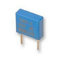
CAPACITOR, 1UF 63V CAPACITOR, 1UF 63V
Manufacturer
Vishay
Series
2222370r
Datasheet
1.2222_370_11105.pdf
(18 pages)
Specifications of 2222 370 11105
Capacitance
1UF
Voltage Rating, Ac
40V
Voltage Rating, Dc
63V
Capacitor Dielectric Type
POLYESTER
Tolerance,
10%
Tolerance, -
10%
Temp, Op. Max
100(DEGREE C)
Temp, Op.
ROHS COMPLIANT


HEAT CONDUCTIVITY (G) AS A FUNCTION OF (ORIGINAL) PITCH AND CAPACITOR BODY THICKNESS IN mW/°C
POWER DISSIPATION AND MAXIMUM COMPONENT TEMPERATURE RISE
The power dissipation must be limited in order not to exceed the maximum allowed component temperature rise as a function of
the free ambient temperature.
The power dissipation can be calculated according type detail specification “HQN-384-01/101: Technical Information Film
Capacitors”.
The component temperature rise (ΔT) can be measured (see section “Measuring the component temperature” for more details)
or calculated by ΔT = P/G:
MEASURING THE COMPONENT TEMPERATURE
A thermocouple must be attached to the capacitor body as in:
The temperature is measured in unloaded (T
The temperature rise is given by ΔT = T
To avoid radiation or convection, the capacitor should be tested in a wind-free box.
APPLICATION NOTE AND LIMITING CONDITIONS
These capacitors are not suitable for mains applications as across-the-line capacitors without additional protection, as described
hereunder. These mains applications are strictly regulated in safety standards and therefore electromagnetic interference
suppression capacitors conforming the standards must be used.
To select the capacitor for a certain application, the following conditions must be checked:
1. The peak voltage (U
2. The peak-to-peak voltage (U
3. The voltage peak slope (dU/dt) shall not exceed the rated voltage pulse slope in an RC-circuit at rated voltage and without
4. The maximum component surface temperature rise must be lower than the limits (see figure max. allowed component
5. Since in circuits used at voltages over 280 V peak-to-peak the risk for an intrinsically active flammability after a capacitor
6. When using these capacitors as across-the-line capacitor in the input filter for mains applications or as series connected with
Document Number: 28108
Revision: 08-Dec-08
ringing. If the pulse voltage is lower than the rated DC voltage, the rated voltage pulse slope may be multiplied by U
divided by the applied voltage.
For all other pulses following equation must be fulfilled:
T is the pulse duration
temperature rise).
breakdown (short circuit) increases, it is recommended that the power to the component is limited to 100 times the values
mentioned in the table: “Heat conductivity”
an impedance to the mains the applicant must guarantee that the following conditions are fulfilled in any case (spikes and
surge voltages from the mains included).
• ΔT = Component temperature rise (°C)
• P = Power dissipation of the component (mW)
• G = Heat conductivity of the component (mW/°C)
P
) shall not be greater than the rated DC voltage (U
.
W
(mm)
2.5
3.5
4.5
6.0
max.
P-P
) shall not be greater than 2
C
- T
For technical questions, contact: dc-film@vishay.com
amb
amb
MKT Radial Potted Type
.
) and maximum loaded condition (T
DC Film Capacitor
2 x
√
T
∫
0
2 x U
⎛
⎝
dU
------ -
dt
Thermocouple
⎞
⎠
2
Rac
x dt
to avoid the ionisation inception level
<
Rdc
U
Rdc
)
HEAT CONDUCTIVITY (mW/°C)
x
⎛
⎝
C
dU
------ -
dt
).
⎞
⎠
rated
PITCH 5 mm
Vishay BCcomponents
2.5
3.0
4.0
5.5
MKT 370
www.vishay.com
Rdc
and
89
Related parts for 2222 370 11105
Image
Part Number
Description
Manufacturer
Datasheet
Request
R

Part Number:
Description:
CAPACITOR, 0.15UF 63V CAPACITOR, 0.15UF 63V
Manufacturer:
Vishay
Datasheet:
Part Number:
Description:
CAPACITOR, 0.47UF 63V CAPACITOR, 0.47UF 63V
Manufacturer:
Vishay
Datasheet:
Part Number:
Description:
CAPACITOR, 0.15UF 100V CAPACITOR, 0.15UF 100V
Manufacturer:
Vishay
Datasheet:
Part Number:
Description:
CAPACITOR, 0.22UF 100V CAPACITOR, 0.22UF 100V
Manufacturer:
Vishay
Datasheet:
Part Number:
Description:
CAPACITOR, 0.33UF 100V CAPACITOR, 0.33UF 100V
Manufacturer:
Vishay
Datasheet:
Part Number:
Description:
CAPACITOR, 0.47UF 100V CAPACITOR, 0.47UF 100V
Manufacturer:
Vishay
Datasheet:
Part Number:
Description:
CAPACITOR, 0.01UF 250V CAPACITOR, 0.01UF 250V
Manufacturer:
Vishay
Datasheet:
Part Number:
Description:
CAPACITOR, 0.0047UF 250V CAPACITOR, 0.0047UF 250V
Manufacturer:
Vishay
Datasheet:
Part Number:
Description:
CAPACITOR, 0.001UF 400V CAPACITOR, 0.001UF 400V
Manufacturer:
Vishay
Datasheet:
Part Number:
Description:
CAPACITOR, 0.0015UF 400V CAPACITOR, 0.0015UF 400V
Manufacturer:
Vishay
Datasheet:

Part Number:
Description:
357-036-542-201 CARDEDGE 36POS DL .156 BLK LOPRO
Manufacturer:
Vishay
Datasheet:
Part Number:
Description:
357-036-542-201 CARDEDGE 36POS DL .156 BLK LOPRO
Manufacturer:
Vishay
Datasheet:
Part Number:
Description:
357-036-542-201 CARDEDGE 36POS DL .156 BLK LOPRO
Manufacturer:
Vishay
Datasheet:
Part Number:
Description:
357-036-542-201 CARDEDGE 36POS DL .156 BLK LOPRO
Manufacturer:
Vishay
Datasheet:
Part Number:
Description:
357-036-542-201 CARDEDGE 36POS DL .156 BLK LOPRO
Manufacturer:
Vishay
Datasheet: