TAJW105K050RNJ AVX Corporation, TAJW105K050RNJ Datasheet
TAJW105K050RNJ
Specifications of TAJW105K050RNJ


Related parts for TAJW105K050RNJ

TAJW105K050RNJ Summary of contents
Page 1
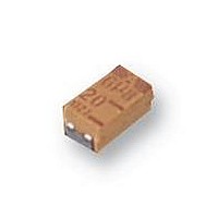
... TAJ Series Low Profile TAJ low profile solid tantalum chip capacitors are designed for boards with limited height. The capacitors are avail- able in maximum height of 1.0, 1.2, 1.5 and 2.0mm. For part marking see page 177 HOW TO ORDER TAJ Y 107 Type ...
Page 2
TAJ Series Low Profile CAPACITANCE AND VOLTAGE RANGE, V (LETTER DENOTES CASE SIZE) Capacitance μF Code 2.5V (e) 4V (G) 0.10 104 0.15 154 0.22 224 0.33 334 0.47 474 0.68 684 1.0 105 1.5 155 2.2 225 R/S 3.3 ...
Page 3
TAJ Series Low Profile RATINGS & PART NUMBER REFERENCE Rated AVX Case Capacitance Voltage Part No. Size (μF) (V) TAJR475*002# R 4.7 2.5 TAJR685*002# R 6.8 2.5 TAJR106*002 2.5 TAJS106*002 2.5 TAJR156*002 2.5 TAJP226*002# ...
Page 4
TAJ Series Low Profile RATINGS & PART NUMBER REFERENCE Rated AVX Case Capacitance Voltage Part No. Size (μF) (V) TAJT156*010 TAJW156*010 TAJT226*010 TAJW226*010 TAJW336*010 TAJW476*010# ...
Page 5
TAJ Series Low Profile RATINGS & PART NUMBER REFERENCE Rated AVX Case Capacitance Voltage Part No. Size (μF) (V) TAJW335*035# W 3.3 35 TAJW475*035# W 4.7 35 TAJY685*035# Y 6.8 35 TAJX106*035 TAJY106*035 TAJY156*035# ...