B64290L618X37 EPCOS Inc, B64290L618X37 Datasheet - Page 4
B64290L618X37
Manufacturer Part Number
B64290L618X37
Description
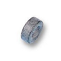
FERRITE RING CORE, 25.3X14.8X10
Manufacturer
EPCOS Inc
Datasheet
1.B64290L618X37.pdf
(5 pages)
Specifications of B64290L618X37
Impedance
0ohm
Ferrite Grade
T37
Svhc
No SVHC (18-Jun-2010)
Ae Effective Cross Section Area
51.26mm2
Al Tolerance Value +
25%
Effective Magnetic Path Length
60.07mm
External Diameter
25.3mm
Lead Free Status / RoHS Status
Lead free / RoHS Compliant


Mechanical stress and mounting
Ferrite cores have to meet mechanical requirements during assembling and for a growing number
of applications. Since ferrites are ceramic materials one has to be aware of the special behavior
under mechanical load.
As valid for any ceramic material, ferrite cores are brittle and sensitive to any shock, fast changing
or tensile load. Especially high cooling rates under ultrasonic cleaning and high static or cyclic loads
can cause cracks or failure of the ferrite cores.
For detailed information see Data Book 2007, chapter “General – Definitions, 8.1”.
Effects of core combination on A
Stresses in the core affect not only the mechanical but also the magnetic properties. It is apparent
that the initial permeability is dependent on the stress state of the core. The higher the stresses are
in the core, the lower is the value for the initial permeability. Thus the embedding medium should
have the greatest possible elasticity.
For detailed information see Data Book 2007, chapter “General – Definitions, 8.2”.
Heating up
Ferrites can run hot during operation at higher flux densities and higher frequencies.
NiZn-materials
The magnetic properties of NiZn-materials can change irreversible in high magnetic fields.
Processing notes
– The start of the winding process should be soft. Else the flanges may be destroid.
– To strong winding forces may blast the flanges or squeeze the tube that the cores can no more
– To long soldering time at high temperature (>300 °C) may effect coplanarity or pin arrangement.
– Not following the processing notes for soldering of the J-leg terminals may cause solderability
– The dimensions of the hole arrangement have fixed values and should be understood as a
Ferrites and accessories
Cautions and warnings
be mount.
problems at the transformer because of pollution with Sn oxyd of the tin bath or burned insulation
of the wire. For detailed information see Data Book 2007, chapter “Processing notes, 2.2”.
recommendation for drilling the printed circuit board. For dimensioning the pins, the group of
holes can only be seen under certain conditions, as they fit into the given hole arrangement. To
avoid problems when mounting the transformer, the manufacturing tolerances for positioning the
customers’ drilling process must be considered by increasing the hole diameter.
L
value
4
09/06
Related parts for B64290L618X37
Image
Part Number
Description
Manufacturer
Datasheet
Request
R

Part Number:
Description:
Manufacturer:
EPCOS Inc
Datasheet:


Part Number:
Description:
CAP .15UF 63V METAL POLY
Manufacturer:
EPCOS Inc
Datasheet:


Part Number:
Description:
CAP .01UF 400V METAL POLY
Manufacturer:
EPCOS Inc
Datasheet:
