PM105SB-390L-RC Bourns Inc., PM105SB-390L-RC Datasheet - Page 2
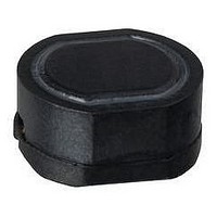
PM105SB-390L-RC
Manufacturer Part Number
PM105SB-390L-RC
Description
POWER INDUCTOR, 39UH 1.1A 15% 14MHZ
Manufacturer
Bourns Inc.
Series
PM105SBr
Datasheet
1.PM105SB-470L-RC.pdf
(2 pages)
Specifications of PM105SB-390L-RC
Inductance Tolerance
± 15%
Dc Resistance Max
0.12ohm
Dc Current Rating
1.1A
Self Resonant Frequency
14MHz
Core Material
Ferrite
Inductor Case Style
SMD
No. Of Pins
2
Inductance
39µH
Tolerance
15 %
Maximum Dc Current
1.1 Amps
Maximum Dc Resistance
0.12 Ohms
Dimensions
9 mm W x 10 mm L x 5 mm H
Shielding
Shielded
Operating Temperature Range
- 30 C to + 100 C
Termination Style
SMD/SMT
Test Frequency
2.52 MHz
Lead Free Status / RoHS Status
Lead free / RoHS Compliant


REV. 05/09
Specifi cations are subject to change without notice.
Customers should verify actual device performance in their specifi c applications
Packaging Specifi cations
Soldering Profi le
275
225
175
125
75
25
PM105SB Series - Shielded SMD Power Inductor
END
0
150°C
<1> Maximum of 10 seconds between
+255°C and +260°C
NO COMPONENT
(7.87)
200
50
(12.992)
330.0
DIA.
Ramp Up
3°C/second maximum
(.827 ± .032)
21.0 ± 0.8
(.512 ± .020)
13.0 ± 0.5
120 - 150 seconds
100
DIA.
(.079 ± .020)
(.630)
190°C
2.0 ± 0.5
16.0
USER DIRECTION OF FEED
Time (seconds)
QTY: 500 PCS. PER REEL
<1> 255°C
220°C
150
10 seconds minimum
COMPONENTS
(.512 ± .020)
13.0 ± 0.5
(1.023 + 0)
(.157)
seconds
(1.197)
26. + 0
60 - 90
4.0
DIA.
30.4
200
260°C peak
(1.969 - 0)
50.0 - 0
250
Ramp Down
6°C/second
maximum
Rev. 02/22/05
300
NO COMPONENT
(15.75)
400
Electrical Schematic
START
DIMENSIONS:
(INCHES)
MM
Related parts for PM105SB-390L-RC
Image
Part Number
Description
Manufacturer
Datasheet
Request
R

Part Number:
Description:
POWER CHOKE, SHIELDED
Manufacturer:
Bourns Inc.
Datasheet:
Part Number:
Description:
Power Inductors 390uH 10%
Manufacturer:
Bourns Inc.
Datasheet:

Part Number:
Description:
Power Inductors 390uH 10%
Manufacturer:
Bourns Inc.
Datasheet:
Part Number:
Description:
Power Inductors 100uH 10%
Manufacturer:
Bourns Inc.
Datasheet:
Part Number:
Description:
Power Inductors 56uH 15%
Manufacturer:
Bourns Inc.
Datasheet:
Part Number:
Description:
Power Inductors 15uH 20%
Manufacturer:
Bourns Inc.
Datasheet:

Part Number:
Description:
Power Inductors 10uH 20%
Manufacturer:
Bourns Inc.
Datasheet:
Part Number:
Description:
Power Inductors 120uH 10%
Manufacturer:
Bourns Inc.
Datasheet:
Part Number:
Description:
Power Inductors 68uH 15%
Manufacturer:
Bourns Inc.
Datasheet:
Part Number:
Description:
Power Inductors 330uH 10%
Manufacturer:
Bourns Inc.
Datasheet:

Part Number:
Description:
Manufacturer:
Bourns, Inc.
Datasheet:
Part Number:
Description:
11mm Potentiometer
Manufacturer:
Bourns, Inc.
Datasheet: