29 0001 ALPS, 29 0001 Datasheet - Page 3
29 0001
Manufacturer Part Number
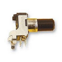
29 0001
Description
POTENTIOMETER, 10KB
Manufacturer
ALPS
Series
RK09r
Datasheet
1.29_0001.pdf
(5 pages)
Specifications of 29 0001
Track Resistance
10kohm
Track Taper
Linear
No. Of Turns
1
Resistance Tolerance
± 20%
Voltage Rating
20V
Power Rating
50mW
No. Of Gangs
1
Resistor Element
RoHS Compliant
Adjustment Type
Horizontal
Potentiometer Mounting
PCB
Rohs Compliant
Yes


SfHB
ELECTRICAL
MECHANICAL
EKDURANCE
NOTE
I
4.Residual
8. Taper
2. Rated power
3. Rated voI tage
5. Slidins
6. Insulat ion
7. Wi thstand voltage: More
2. Ooerat ion
3. Shaf.
4. Star t i ng
8-Rabtstness of
5. Resistance
5. Play of
7. Eccentr ici ty of
9. Robustness of
!. Total
1. Overal I
2. Operating temperature :-!0°C~+60° C. 3. Storage temperature :~30 C~+70 C
!. The items except above menjionedoiterns shall meet or exceed Jt£ C 6443.
OA'E
1- -Rotal ional
After soldering
evidence ol
The resistor shall
and a side thrust of 250 gf-cm at
physical
The eccentricity of
center
"he shaft
3
The shaft shall withstand asainst side thrust of not
3 seconds on the end ol
alter mounting
then the total Play of the shaft shall not exceed
The rated voltage shall
honever.
rated volta»e exceeds
seconds.
(commercial
(d i ss i oat ion). and be obtained from the
Where
Maximum
APP0
end
resistance :
of
\
noise
rotat iona I
shaft
ICHK0
damages as a result of
toruaue
the mounting
shall mthstand against end thrust of not
stoo
toraue
the maximum
resistance
to solderin9
ooor
resistance
working voltase
i ^
E = fP7
E : Rated voltage
P : Rated cower (d issi oat ion)
R : Nominal
freauency .effective value
life
between
osco
shaft
shaft
the
strength
(Less than
contact
shaf t
=
= 0. 05 w
:
:
: B
be mounted by soldering
resistor
the root of shaft shall
antil e
Set. 13.'U
APPD.
10k a ±20»
S.
Less
against
a9ainst
position.
grking voltaee ol
the maximum working voltage given in the
:
the shalt at ri9ht angles to the axis of the shaft
:
SPECIFICATIONS
between
5. 000 eye les mi n.
(V)
term. I & 2.
be the voltase
Greater than 100 Mo measured by D. C. 250V.
than I minute with an application of A. C 250
heat
oetween
300°C and quicker than 3
total
than
' 280 ±5
:
:
:
by soldering.
3
10-80 flf-cm
100 gf -cm MAX.
CHKD-
Set. 13.' $S
M. S31 oh
end
:
side thrust
Kfl f • cm MIN.
:
the test.
ALPS ELECTRIC CO., LTD.
50 V A. C.
resistance element
100 mV measured
the end of
resistance
IV)
thrust
terminals
term.2&3
I Ssiloh
osco.
See. 13. ' Si
)
of 0. C.
f ol I onino
I
the
corresponding
the mounting
:
not exceed 0.35mm asainst
.
:
the shaft shall
following shall
20 V D. C.
(W)
(Q)
I
or A. C.
TITLE
DOCUMENT
0. 5 x L / 20 mm p-d.
W I 0 1 I 7 5 2M
by method of JIS C 6443.
formula.
:
seconds)
and
less than 5 Ksf
less than 4 Kjf-cm for
3000
terminals.
less on the oanel.
to
NO.
When the obtained
the rated Power
there
be aoolied.
max.
be
fol lowing.
the rated vol ta«e.
or
shall
lor
any
the
be
no
Related parts for 29 0001
Image
Part Number
Description
Manufacturer
Datasheet
Request
R

Part Number:
Description:
POTENTIOMETER, 10KA
Manufacturer:
ALPS
Datasheet:
Part Number:
Description:
POTENTIOMETER, 10KA
Manufacturer:
ALPS
Datasheet:

Part Number:
Description:
POTENTIOMETER, 10KB
Manufacturer:
ALPS
Datasheet:
Part Number:
Description:
POTENTIOMETER, 100KB
Manufacturer:
ALPS
Datasheet:
