TSM4YJ104KB25 Vishay, TSM4YJ104KB25 Datasheet - Page 2
TSM4YJ104KB25
Manufacturer Part Number
TSM4YJ104KB25
Description
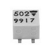
POT, TRIM, 100KOHM 13TURN, 10%, SMD
Manufacturer
Vishay
Type
Trimmerr
Datasheet
1.TSM4YJ104KB25.pdf
(4 pages)
Specifications of TSM4YJ104KB25
Track Resistance
100kohm
No. Of Turns
11
Resistance Tolerance
± 10%
Power Rating
250mW
Potentiometer Mounting
SMD
Temperature Coefficient
± 100ppm/°C
Resistance
100kohm
Tolerance (+ Or -)
10%
Number Of Turns
11Turn
Technology
Cermet
Mounting Style
Surface Mount
Termination Style
J-Hook
Operating Temp Range
-55C to 125C
Failure Rate
Not Required
Shaft Diameter (mm)
1.5mm
Product Diameter (mm)
Not Requiredmm
Product Length (mm)
4.8mm
Product Height (mm)
5.3mm
Product Depth (mm)
3.8mm
Lead Free Status / RoHS Status
Lead free / RoHS Compliant


www.vishay.com
22
TSM4
Vishay Sfernice
MECHANICAL SPECIFICATIONS
Mechanical Travel
Operating Torque (max. Ncm) 1
End Stop Torque (Ncm)
Unit Weight (max. g)
Wiper (actual travel)
ENVIRONMENTAL SPECIFICATIONS
Temperature Range
Climatic Category
Sealing
MSL Level
ELECTRICAL SPECIFICATIONS
Resistive Element
Electrical Travel
Resistance Range
Standard Series
Tolerance Standard
Power Rating
Temperature Coefficient
Limiting Element Voltage (Linear Law)
Contact Resistance Variation (Typical)
End Resistance (Typical)
Dielectric Strength (RMS)
Insulation Resistance
PERFORMANCE
TESTS
Load Life
Moisture Resistance
Long Term Damp Heat
Thermal Shock
Rotational Life (Electrical and Mechanical)
Shock
Vibration
Linear
Logarithmic
13 turns ± 2
clutch action (2 turns max)
0.15
positioned at approx. 50 %
- 55 °C to + 125 °C
55/125/56
sealed container
solder immersion IP67
1
Surface Mount Miniature Trimmers
For technical questions, contact: sfer@vishay.com
90'/30' - ambient temperature + 85 °C
3 successive shocks in 3 directions
with damp heat - cold - vibrations
Multi-Turn Cermet Sealed
10 cycles of 24 hours constituted
Temperature 40 °C - RH 93 %
- 55 °C to + 125 °C - 5 cycles
MIL STD 202 Method 204/D
MIL STD 202 Method 213/1
1000 hours at rated power
MIL STD 202 Method 106
100 cycles - rated power
See also: Application notes
20 g - 12 hours
CONDITIONS
100 g - 6 ms
56 days
POWER RATING CHART
See Standard Resistance Element Table
0.125
0.25
0
0
0.25 W at + 85 °C
Not applicable
10 Ω to 1 MΩ
AMBIENT TEMPERATURE IN DEGREES CELSIUS
11 turns ± 2
± 2 %
Contact resistance variation: Δ > 1 % Rn
± 2 %
Dielectric strength: 1000 V RMS
Insulation resistance: > 10
± 2 %
Dielectric strength: 1000 V
Insulation resistance: > 10
± 1 %
± (3 % + 3 Ω)
± 1 %
± 1 %
2 % or 3 Ω
20
1 - 2 - 5
Cermet
10
± 10 %
200 V
600 V
1 Ω
6
MΩ
40
TYPICAL VALUES AND DRIFTS
ΔRT
RT
60
(%)
85
Document Number: 51009
100
4
4
RMS
MΩ
MΩ
Revision: 02-Oct-07
120
± 3 %
± 3 %
± 3 %
ΔR
ΔV
ΔV
ΔV
R
V
V
V
140
1-2
1-2
1-2
1-3
1-2
1-3
1-2
1-3
(%)
≤ ± 2 %
≤ ± 1 %
≤ ± 1 %
155
Related parts for TSM4YJ104KB25
Image
Part Number
Description
Manufacturer
Datasheet
Request
R

Part Number:
Description:
357-036-542-201 CARDEDGE 36POS DL .156 BLK LOPRO
Manufacturer:
Vishay
Datasheet:
Part Number:
Description:
357-036-542-201 CARDEDGE 36POS DL .156 BLK LOPRO
Manufacturer:
Vishay
Datasheet:
Part Number:
Description:
357-036-542-201 CARDEDGE 36POS DL .156 BLK LOPRO
Manufacturer:
Vishay
Datasheet:
Part Number:
Description:
357-036-542-201 CARDEDGE 36POS DL .156 BLK LOPRO
Manufacturer:
Vishay
Datasheet:
Part Number:
Description:
357-036-542-201 CARDEDGE 36POS DL .156 BLK LOPRO
Manufacturer:
Vishay
Datasheet:
Part Number:
Description:
357-036-542-201 CARDEDGE 36POS DL .156 BLK LOPRO
Manufacturer:
Vishay
Datasheet:
Part Number:
Description:
357-036-542-201 CARDEDGE 36POS DL .156 BLK LOPRO
Manufacturer:
Vishay
Datasheet:
Part Number:
Description:
357-036-542-201 CARDEDGE 36POS DL .156 BLK LOPRO
Manufacturer:
Vishay
Datasheet:
Part Number:
Description:
357-036-542-201 CARDEDGE 36POS DL .156 BLK LOPRO
Manufacturer:
Vishay
Datasheet:
Part Number:
Description:
357-036-542-201 CARDEDGE 36POS DL .156 BLK LOPRO
Manufacturer:
Vishay
Datasheet:
Part Number:
Description:
357-036-542-201 CARDEDGE 36POS DL .156 BLK LOPRO
Manufacturer:
Vishay
Datasheet:
Part Number:
Description:
357-036-542-201 CARDEDGE 36POS DL .156 BLK LOPRO
Manufacturer:
Vishay
Datasheet:
Part Number:
Description:
357-036-542-201 CARDEDGE 36POS DL .156 BLK LOPRO
Manufacturer:
Vishay
Datasheet:
Part Number:
Description:
357-036-542-201 CARDEDGE 36POS DL .156 BLK LOPRO
Manufacturer:
Vishay
Datasheet:
Part Number:
Description:
357-036-542-201 CARDEDGE 36POS DL .156 BLK LOPRO
Manufacturer:
Vishay
Datasheet: