MDP160110K0GD04 Vishay, MDP160110K0GD04 Datasheet - Page 3
MDP160110K0GD04
Manufacturer Part Number
MDP160110K0GD04
Description
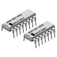
RESISTOR, BUS RES N/W 15, 10KOHM, 2%, DIP
Manufacturer
Vishay
Series
MDPr
Specifications of MDP160110K0GD04
Resistance
10kohm
Resistance Tolerance
± 2%
Power Rating
125mW
Voltage Rating
100V
Temperature Coefficient
± 100ppm/°C
No. Of Elements
15
Resistor Case Style
DIP
Product Type
Networks
Circuit Type
Bussed
Number Of Resistors
15
Tolerance
2 %
Number Of Pins
16
Package / Case
DIP-16
Operating Temperature Range
- 55 C to + 125 C
Dimensions
7.87 mm W x 19.05 mm L x 3.05 mm H
Lead Spacing
2.54 mm
Termination Style
DIP
Lead Free Status / RoHS Status
Contains lead / RoHS non-compliant


www.vishay.com
3
MDP 01, 03, 05
Vishay Dale
Standard E-24 resistance values stocked. Consult factory
01 SCHEMATIC
03 SCHEMATIC
05 SCHEMATIC
IMPEDANCE CODES
CIRCUIT APPLICATIONS
CODE
500B
750B
800C
990A
101C
111C
121B
121C
131A
Pin #1
R2
R1
R1
R2
R2
Pin #1
Pin #1
R1
R1
R2
R2
MDP1405, MDP1605
R1
R1
•
R2
R2
MDP1403
•
R1(Ω)
MDP1603
R1
120
130
160
180
180
180
220
220
MDP1401
R1
82
•
MDP1601
•
R2 R2
R2
•
Thick Film Resistor Networks, Dual-In-Line,
R1
R1
•
For technical questions contact: ff2aresistors@vishay.com
R2
•
Molded DIP, 01, 03, 05 Schematics
R1
R2
R1
•
R2
R1
R2
R1
R2(Ω)
130
200
210
260
240
270
390
270
330
The MDPXX01 circuit provides a choice of 13 and 15 nominally equal
resistors, each connected between a common pin (14 and 16) and a
discrete PC board pin. Commonly used in the following applications:
• MOS/ROM Pull-up/Pull-down
• Open Collector Pull-up
• "Wired OR" Pull-up
• Power Driven Pull-up
The MDPXX03 provides a choice of 7 and 8 nominally equal resistors,
each resistor isolated from all others and wired directly across.
Commonly used in the following applications:
• "Wired OR" Pull-up
• Power Driven Pull-up
• Powergate Pull-up
• Line Termination
The MDPXX05 circuit contains 12 and 14 series pair of resistors.
Each series pair is connected between ground and a common line.
The junction of these resistor pairs is connected to the input terminals.
The 05 circuits are designed for TTL dual-line termination and pulse
squaring.
CODE
141A
181A
191A
221B
281B
381B
501C
102A
202B
13 and 15 resistors with one pin common
TTL dual-line terminator; pulse squaring
7 and 8 isolated resistors
R1(Ω)
1.5K
270
330
330
330
560
560
620
3K
• Long-line Impedance Balancing
• LED Current Limiting
• ECL Output Pull-down
• TTL Input Pull-down
• TTL Input Pull-down
• Digital Pulse Squaring
• TTL Unused Gate Pull-up
• High Speed Parallel Pull-up
Document Number: 31511
Revision: 28-Jul-06
R2(Ω)
1.2K
2.7K
3.3K
6.2K
270
390
470
680
560
Related parts for MDP160110K0GD04
Image
Part Number
Description
Manufacturer
Datasheet
Request
R

Part Number:
Description:
357-036-542-201 CARDEDGE 36POS DL .156 BLK LOPRO
Manufacturer:
Vishay
Datasheet:
Part Number:
Description:
357-036-542-201 CARDEDGE 36POS DL .156 BLK LOPRO
Manufacturer:
Vishay
Datasheet:
Part Number:
Description:
357-036-542-201 CARDEDGE 36POS DL .156 BLK LOPRO
Manufacturer:
Vishay
Datasheet:
Part Number:
Description:
357-036-542-201 CARDEDGE 36POS DL .156 BLK LOPRO
Manufacturer:
Vishay
Datasheet:
Part Number:
Description:
357-036-542-201 CARDEDGE 36POS DL .156 BLK LOPRO
Manufacturer:
Vishay
Datasheet:
Part Number:
Description:
357-036-542-201 CARDEDGE 36POS DL .156 BLK LOPRO
Manufacturer:
Vishay
Datasheet:
Part Number:
Description:
357-036-542-201 CARDEDGE 36POS DL .156 BLK LOPRO
Manufacturer:
Vishay
Datasheet:
Part Number:
Description:
357-036-542-201 CARDEDGE 36POS DL .156 BLK LOPRO
Manufacturer:
Vishay
Datasheet:
Part Number:
Description:
357-036-542-201 CARDEDGE 36POS DL .156 BLK LOPRO
Manufacturer:
Vishay
Datasheet:
Part Number:
Description:
357-036-542-201 CARDEDGE 36POS DL .156 BLK LOPRO
Manufacturer:
Vishay
Datasheet:
Part Number:
Description:
357-036-542-201 CARDEDGE 36POS DL .156 BLK LOPRO
Manufacturer:
Vishay
Datasheet:
Part Number:
Description:
357-036-542-201 CARDEDGE 36POS DL .156 BLK LOPRO
Manufacturer:
Vishay
Datasheet:
Part Number:
Description:
357-036-542-201 CARDEDGE 36POS DL .156 BLK LOPRO
Manufacturer:
Vishay
Datasheet:
Part Number:
Description:
357-036-542-201 CARDEDGE 36POS DL .156 BLK LOPRO
Manufacturer:
Vishay
Datasheet:
Part Number:
Description:
357-036-542-201 CARDEDGE 36POS DL .156 BLK LOPRO
Manufacturer:
Vishay
Datasheet: