NFR2500002201JA500 Vishay, NFR2500002201JA500 Datasheet - Page 8
NFR2500002201JA500
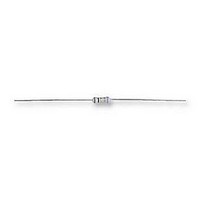
Manufacturer Part Number
NFR2500002201JA500
Description
RESISTOR, FUSIBLE, 2K2
Manufacturer
Vishay
Series
NFR25r
Datasheet
1.NFR2500001000JA500.pdf
(9 pages)
Specifications of NFR2500002201JA500
Resistance
2.2kohm
Resistance Tolerance
± 5%
Power Rating
330mW
Voltage Rating
250V
Resistor Element Material
Metal Film
No. Of Pins
2
Body
RoHS Compliant
Temperature Coefficient
± 100ppm/°C
Resistor Case Style
Axial
Rohs Compliant
Yes


Document Number: 28737
Revision: 21-Feb-08
TEST PROCEDURES AND REQUIREMENTS
IEC
60115-1
CLAUSE
TESTS IN ACCORDANCE WITH THE SCHEDULE OF IEC PUBLICATION 60115-8
4.4.1
4.4.2
4.5
4.18
4.29
4.17
4.7
4.16
4.16.2
4.16.3
4.16.4
4.20
4.22
4.19
4.23
4.23.3
4.23.6
4.24.2
4.25.1
4.25.3
4.8.4.2
4.12
4.26
OTHER TESTS IN ACCORDANCE WITH IEC 60115 CLAUSES AND IEC 60068 TEST METHOD
4.17
4.6.1.1
see 2
to “IEC 60115-1”, Jan.’87
nd
amendment
METHOD
21 (Ua1)
60068-2
21 (Ub)
14 (Na)
30 (Db)
30 (Db)
20 (Tb)
45 (Xa)
21 (Uc)
29 (Eb)
20 (Ta)
21 (U)
3 (Ca)
6 (Fc)
TEST
20 (Ta)
IEC
robustness of terminations:
(refer note on first page for
voltage proof on insulation
damp heat (accelerated)
damp heat (accelerated)
bending half number of
resistance to soldering
temperature coefficient
measuring distance)
dimensions (outline)
category temperature
endurance (at 70 °C)
torsion other half of
(steady state) (IEC)
insulation resistance
component solvent
visual examination
tensile all samples
climatic sequence:
endurance at upper
accidental overload
remaining cycles
rapid change of
temperature
(after ageing)
solderability
damp heat
solderability
resistance
resistance
For technical questions, contact: filmresistors.leaded@vishay.com
pulse load
samples
samples
vibration
1
TEST
bump
st
heat
noise
cycle
Fusible, Non-Flammable Resistors
displacement 1.5 mm or acceleration
brushing in accordance with “MIL 202 F”
isopropyl alcohol or H
3 x 1500 bumps in 3 directions; 40 g
maximum voltage U
56 days; 40 °C; 90 % to 95 % RH;
6 days; 55 °C; 95 % to 98 % RH
3 x 360° in opposite directions
after 1 min; metal block method
20/UCT/20 °C (TCR x 10
applied voltage (+ 0/- 10 %):
in a solder bath at 235 ± 5 °C
frequency 10 Hz to 500 Hz;
thermal shock: 3 s; 350 °C;
1 min; metal block method
10 g; 3 directions; total 6 h
U
10 kΩ ≤ R ≤ 15 kΩ: 10 V
8 h steam or 16 h 155 °C;
10 Ω ≤ R < 100 Ω: 0.3 V
30 min at UCT; 5 cycles
1.5 h ON and 0.5 h OFF
loaded with Pn or V
“IEC publication 60195”
100 Ω ≤ R < 1 kΩ: 1 V
1 kΩ ≤ R < 10 kΩ: 3 V
(IEC steps: 4 to 100 V)
RMS
leads immersed 6 mm
at 20/LCT/20 °C and
30 min at LCT and
loaded with 0.01 Pn
0.22 Ω ≤ R ≤ 4.7 Ω
load 5 N; 4 x 90°
3 mm from body
15 Ω < R ≤ 15 kΩ
R < 10 Ω: 0.1 V
4.7 Ω < R ≤ 15 Ω
load 10 N; 10 s
PROCEDURE
= 500 V
gauge (mm)
cheese-cloth
2 s; 235 °C
for 2 ± 0.5 s
(3 x 2 h)
1000 h;
1000 h;
no load
RMS
max.
2
O followed by
during
DC = 500 V
max.
−6
;
/K):
≤ ± 200 x 10
≤ ± 200 x 10
≤ ± 100 x 10
Vishay BCcomponents
no holes; clean surface; no damage
see the Pulse Loading Capabilities
ΔR max.: ± (0.25 % R + 0.05 Ω)
ΔR max.: ± (0.25 % R + 0.05 Ω)
ΔR max.: ± (0.25 % R + 0.05 Ω)
ΔR max.: ± (0.25 % R + 0.05 Ω)
number of failures < 10 x 10
number of failures < 10 x 10
ΔR max.: ± (0.25 % + 0.05 Ω)
good tinning (≥ 95 % covered);
NFR25
ΔR max.: ± (1 % R + 0.05 Ω)
ΔR max.: ± (1 % R + 0.05 Ω)
ΔR max.: ± (1 % R + 0.05 Ω)
ΔR max.: ± (1 % R + 0.05 Ω)
no breakdown or flashover
good tinning; no damage
see Dimensions Table
R - R
R
REQUIREMENTS
R
no visual damage
R
no visual damage
ins
ins
ins
nonflammable
-6
-6
-6
no damage
no damage
no damage
max.: 1000 MΩ
nom
< 0.1 µV/V
/K
/K
no damage
/K
min.: 10
min.: 10
graphs
: max. ± 5 %
NFR25/25H
≤ ± 200 x 10
≤ ± 100 x 10
≤ ± 100 x 10
3
4
MW
MΩ
www.vishay.com
NFR25H
−6
−6
-6
-6
-6
/K
/K
/K
133
Related parts for NFR2500002201JA500
Image
Part Number
Description
Manufacturer
Datasheet
Request
R

Part Number:
Description:
357-036-542-201 CARDEDGE 36POS DL .156 BLK LOPRO
Manufacturer:
Vishay
Datasheet:
Part Number:
Description:
357-036-542-201 CARDEDGE 36POS DL .156 BLK LOPRO
Manufacturer:
Vishay
Datasheet:
Part Number:
Description:
357-036-542-201 CARDEDGE 36POS DL .156 BLK LOPRO
Manufacturer:
Vishay
Datasheet:
Part Number:
Description:
357-036-542-201 CARDEDGE 36POS DL .156 BLK LOPRO
Manufacturer:
Vishay
Datasheet:
Part Number:
Description:
357-036-542-201 CARDEDGE 36POS DL .156 BLK LOPRO
Manufacturer:
Vishay
Datasheet:
Part Number:
Description:
357-036-542-201 CARDEDGE 36POS DL .156 BLK LOPRO
Manufacturer:
Vishay
Datasheet:
Part Number:
Description:
357-036-542-201 CARDEDGE 36POS DL .156 BLK LOPRO
Manufacturer:
Vishay
Datasheet:
Part Number:
Description:
357-036-542-201 CARDEDGE 36POS DL .156 BLK LOPRO
Manufacturer:
Vishay
Datasheet:
Part Number:
Description:
357-036-542-201 CARDEDGE 36POS DL .156 BLK LOPRO
Manufacturer:
Vishay
Datasheet:
Part Number:
Description:
357-036-542-201 CARDEDGE 36POS DL .156 BLK LOPRO
Manufacturer:
Vishay
Datasheet:
Part Number:
Description:
357-036-542-201 CARDEDGE 36POS DL .156 BLK LOPRO
Manufacturer:
Vishay
Datasheet:
Part Number:
Description:
357-036-542-201 CARDEDGE 36POS DL .156 BLK LOPRO
Manufacturer:
Vishay
Datasheet:
Part Number:
Description:
357-036-542-201 CARDEDGE 36POS DL .156 BLK LOPRO
Manufacturer:
Vishay
Datasheet:
Part Number:
Description:
357-036-542-201 CARDEDGE 36POS DL .156 BLK LOPRO
Manufacturer:
Vishay
Datasheet:
Part Number:
Description:
357-036-542-201 CARDEDGE 36POS DL .156 BLK LOPRO
Manufacturer:
Vishay
Datasheet: