WDBR2-150RKT Welwyn Components, WDBR2-150RKT Datasheet
WDBR2-150RKT
Manufacturer Part Number
WDBR2-150RKT
Description
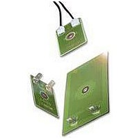
RESISTORS, POWER PLANAR, 150R 2KW RESISTORS, POWER PLANAR, 150R 2KW
Manufacturer
Welwyn Components
Series
WDBRr
Datasheet
1.WDBR1-47RKT.pdf
(3 pages)
Specifications of WDBR2-150RKT
Resistors Element Type
THICK FILM
Resistance
150R
Case Style
PLANAR
Power Rating
200W
Tolerance, +
10%
Tolerance, -
10%
Voltage Rating, Dc
2500V
Rohs Compliant
YES


Ultra Low Profile
Power Resistors
WDBR Series
Electrical Data
Notes:
Physical Data
Construction
A high integrity dielectric layer is applied to a machined
stainless steel substrate. Thick-film conductor and resistor
patterns are printed and fired, then protected with a high
temperature overglaze. The termination pads are tinned with
Pb-free solder and optional terminals or leads are soldered on.
General Note
Welwyn Components reserves the right to make changes in product specification without notice or liability.
All information is subject to Welwyn’s own test data and is considered accurate at time of print.
Welwyn Electronics Park, Bedlington, Northumberland, NE22 7AA, England. Tel: 01670 822181 Fax: 01670 829465 Web: www.welwyn-tt.com
WDBR1/2
WDBR1
WDBR2
WDBR3
WDBR5
WDBR7
Resistance range
Resistance tolerance
Pulse power rating
Power rating on heatsink
Power rating on fan-cooled heatsink
TCR
Maximum element temperature
Dielectric withstand
Inductance (typical)
Dimensions in mm, weight without terminations in g
Welwyn Components Limited
Ultra low profile thick-film on steel
500W to 7kW peak power
Single fixing heatsink mountable
Ideal for dynamic braking, inrush limit and snubber circuits
Choice of flying lead, push-on or solder terminations
Low inductance design
High isolation, even after failsafe overload fusing
RoHS compliant, non-flammable construction
1.
2.
3.
4.
For details of pulse condition see Fig. 1 in Performance Data.
Mounted on a 0.53°C/W heatsink with no forced air cooling, air temperature 25°C.
Mounted on a 0.53°C/W heatsink with 5m/s forced air cooling, air temperature 25°C.
Limited by the solder type; the rating can be improved for non-standard parts by using HMP solder.
101.6
152.4 101.6
L
31.9
49.3
122
61
±0.1
W
1
28.1
35.9
40.6
70
70
±0.1
2
t
V (dc/ac peak)
0.9
1.5
±0.1
ØD nom a nom b nom c nom Wt. nom
ppm/°C
2.2
3.2
5.3
ohms
3
kW
μH
°C
W
%
W
13.5
14.0
15.0
7.5
3.2
4.7
22, 47, 100
WDBR1/2
160
300
0.5
11.2
13.0
22.0
23.8
51.3
3.1
WDBR1
10.2
4.3
6.2
5.8
7.4
9.2
<3
180
700
1.5
181.8
12.6
17.1
50.8
60.7
6.5
12, 22, 47, 100, 150
WDBR2
200
780
2.0
+500 to +600
2500
365
W
10
WDBR3
Substrate thickness = t
Fixing hole is located centrally
260
900
3.5
<4
WDBR5
1000
270
5.0
D
L
<5
47, 100, 150
WDBR7
1490
280
c
7.0
<6
4
4
a
b
Related parts for WDBR2-150RKT
Image
Part Number
Description
Manufacturer
Datasheet
Request
R

Part Number:
Description:
RESISTORS, POWER PLANAR, 100R 2KW RESISTORS, POWER PLANAR, 100R 2KW
Manufacturer:
Welwyn Components
Datasheet:
Part Number:
Description:
RESISTORS, POWER PLANAR, 47R 2KW RESISTORS, POWER PLANAR, 47R 2KW
Manufacturer:
Welwyn Components
Datasheet:
Part Number:
Description:
RESISTORS, POWER PLANAR, 22R 2KW RESISTORS, POWER PLANAR, 22R 2KW
Manufacturer:
Welwyn Components
Datasheet:
Part Number:
Description:
RESISTORS, POWER PLANAR, 12R 2KW RESISTORS, POWER PLANAR, 12R 2KW
Manufacturer:
Welwyn Components
Datasheet:

Part Number:
Description:
RESISTOR, 6K8, 2W, 10%
Manufacturer:
Welwyn Components
Datasheet:

Part Number:
Description:
RESISTOR, DOUBLE SIDED, 1K5, 2010 CASE
Manufacturer:
Welwyn Components
Datasheet:
Part Number:
Description:
RESISTOR, DOUBLE SIDED, 10R, 2512 CASE
Manufacturer:
Welwyn Components
Datasheet:

Part Number:
Description:
RESISTOR, FUSIBLE, 2W, 10R
Manufacturer:
Welwyn Components
Datasheet:
Part Number:
Description:
RESISTOR, FUSIBLE, 2W, 15R
Manufacturer:
Welwyn Components
Datasheet:
Part Number:
Description:
RESISTOR, FUSIBLE, 2W, 27R
Manufacturer:
Welwyn Components
Datasheet:

Part Number:
Description:
Tubular Vitreous Enamelled Wirewound Resistors
Manufacturer:
WELWYN [Welwyn Components Limited]
Datasheet:
Part Number:
Description:
Platinum Temperature Sensor
Manufacturer:
WELWYN [Welwyn Components Limited]
Datasheet:
Part Number:
Description:
High Temperature TaNFilm� Chip Resistors
Manufacturer:
WELWYN [Welwyn Components Limited]
Datasheet:
Part Number:
Description:
High Frequency Chip Resistor Terminators
Manufacturer:
WELWYN [Welwyn Components Limited]
Datasheet:
Part Number:
Description:
Surface Mounted Resistors
Manufacturer:
WELWYN [Welwyn Components Limited]
Datasheet:
WDBR2-150RKT Summary of contents
Page 1
... WDBR2 WDBR3 WDBR5 12, 22, 47, 100, 150 10 2.0 3.5 5.0 200 260 270 780 900 1000 +500 to +600 365 2500 <4 < ...
Page 2
... Thermal grease (e.g. Dow Corning DC340) should be used and the heatsink should have a surface finish of <6.3μm with flatness of <0.05mm. The resistor should be mounted using a screw head bolt of size M5 for WDBR2 & for WDBR1 and M2 for WDBR1/2. This should be torqued to 2.5Nm ±10%. ...
Page 3
... Maximum Single Overload Power 100 10 1 0.1 0.01 0.1 1 Duration of Overload (s) Ordering Procedure Example: WDBR2 at 100 ohms and 10% tolerance with flying leads and packed in a box of 84 pieces: Type Value (use IEC62 code) Tolerance (use IEC62 code) K 10% Termination Solder pad only I L ...