PV5-103-JBQ RCD (RESISTORS COILS DELAYLINES), PV5-103-JBQ Datasheet
PV5-103-JBQ
Manufacturer Part Number
PV5-103-JBQ
Description
RESISTOR, POWER, 10KOHM, 5W, 5%
Manufacturer
RCD (RESISTORS COILS DELAYLINES)
Series
PVr
Datasheet
1.PV10S-100-JBQ.pdf
(1 pages)
Specifications of PV5-103-JBQ
Resistance
10kohm
Resistance Tolerance
± 5%
Power Rating
5W
Voltage Rating
250V
Resistor Element Material
Wirewound
Temperature Coefficient
± 100ppm/°C
Lead Free Status / RoHS Status
Contains lead / RoHS non-compliant
PV SERIES
PVH SERIES
PWV SERIES
OPTIONS
TYPICAL PERFORMANCE CHARACTERISTICS
RCD Components Inc, 520 E.Industrial Park Dr, Manchester, NH, USA 03109
2W TO 25 WATT VERTICAL MOUNT RESISTORS
* Units not to exceed wattage, voltage, or current rating, whichever is less. Voltage determined by E=
voltage rating. Multiply voltage rating by 0.7 for Opt. X. Increased voltage & current ratings available (up to 1KV, 100A).
S
S
P
P
S
O
D
5
M
H
L
O
n i
e T
D
P
P
P
P
P
P
P
E
P
E
P
P
P
P
V
V
P
P
2 (
o
P
E
P
e T
g i
V
p
e i
t p
d
r e
P
P
P
P
V
S
o
Built-in standoffs minimize heat transfer to P.C.B.
Available on exclusive SWIFT
Option X - Non-Inductive
Option E - Low thermal EMF design
Option B - Increased power (refer to chart below)
P
V
W
W
W
W
Option WW or M (wirewound or film element)
Option P - Increased pulse capability
Option FF- Fuse within 10S @50x rated W (custom avail)
m
Industry’s widest range! 1m -1M, to ±.05% 10ppm!
Numerous modifications avail: custom marking,
R
V
R
V
V
V
V
H
H
a
W
W
TC’s to +6000ppm, various lead wire sizes, burn-in, etc.
V
R
W
P
5
r e
s i
c u
1
V
V
V
V
e
h
V
1
H
e l
t a
m
d
H
H
H
H
1
1
V
V
V
V
X
p
E I
1
E I
0
H
P
0
E I
. c
u t
2
3
5
7
V
V
~
t a
1
V
c
e T
a t
0
0
e
0
. p
n i
A
1
1
2
2
i L
2
3
5
7
S
M
1
r t
S
S
0
5
7
e r
n I
S
A
a r
S
n i
0
5
0
5
o
c n
g
0
m
c i
e f
° /
C
d
g
v
0
u t
S
C
R
c u
r e
. p
e
1
1
1
o
(
7
° /
t S
S
W
1 (
1
1
1
e r
e T
W
W
d t
2
3
5
0
0
0
e
7
f e
W
C
e l
o l
a t
W
d t
2
3
5
0
0
0
W
W
W
E
W
W
W
e r
s
0
W
t a
,
t a
.
m
W
W
W
)
W
W
W
a
e v
R
2
2
s i
1
1
p x
0
c n
t a
(
, V
5
7
O
1 (
a t
n
d
(
0
5
0
5
. p
0
s i
a t
3 (
5 (
7 (
1 (
1 (
1 (
a t
O
1 (
g
s l
a t
3 (
4 (
6 (
1 (
1 (
1 (
o
e
t p
0
g
(
e
h t
) A
g
W
W
W
c n
h
t p
2
2
2
s
0
W
a
g
W
W
W
2
2
e
o
(
2
e
B .
W
W
W
u
W
1
e r
)
)
)
a v
e
B .
W
W
W
0 .
0 .
1
e
r u
e r
R
0 .
)
5 .
)
)
)
0 .
0 .
)
)
)
)
)
d
1 .
V
0
0
e
) s
)
)
)
2
. l i
)
x
c u
V
- 1
- 5
- 1
- 5
l o
. s
2
3
5
5
6
6
- 5
M
&
-
m
o t
l o
4
4
1
2
3
5
0
5
0
4
0
0
0 .
0 .
0 .
0 .
e
M
a t
R
8
0 .
9 .
V
a
5
5
0
0
0
a
a
5
0
0
0
0
0
0
d
a t
0
0
a
0
a
2
9
6
l o
. x
g
b
x
2
3
5
4
4
0
0
0
0
0
0
V
V
V
V
V
V
4
9
M
1
4
9
V
g n
4
9
8
. x
7
g
V
V
* e
9
o
5
5
5
0
0
0
V
V
V
V
a t
9
9
) V
0
a
n
* e
0
0
e v
0
0
0
0
e
) H
V
. x
g
V
V
V
V
V
V
* e
C
M
r u
a
S
2
2
3
3
3
1
1
M
2
2
3
3
3
3
x
4
7
2
6
2
2
2
d t
P &PWV
N
8
6
5
4
3
2
O
2
6
2
2
2
2
C
e r
FA053D Sale of this product is in accordance with GF-061. Specifications subject to change without notice.
- 2 Terminal
a
O
A
A
A
A
A
A
A
0
0
0
0
5
0
V
A /
A
A
A
A
A
A
C
. t p
- 4 Terminal
x
r u
t p
- Bracket Mount
M
n
0
0
0
0
0
0
(
2
2
3
3
3
1
1
2 (
3 (
4 (
4 (
4 (
r u
O
1 (
2 (
p
p
p
p
p
p
X .
* t
4
7
2
6
2
2
2
X
a
e r
p
p
p
p
p
p
1
t p
3
TM
A
A
A
A
A
7
2
6
2
0
0
0
D
. x
A
A
e r
m
m
m
m
m
m
X
2
n
) A
) A
) A
) A
) A
) A
) A
0 .
0 .
0 .
e
B .
5 -
5
7
5
n
* t
0 .
0 .
0 .
S
a r
a r
W
W
1
1
1
5 (
5 (
3 (
2 (
2 (
1 (
delivery program!
* t
° 5
)
o t
d t
1
1
1
R
e t
e t
:
:
S
0
0
0
0
0
0
0 .
0 .
0 .
a
2
0 .
0 .
0 .
0 .
0 .
p
p
p
p
p
p
o t
0 .
0 .
0 .
0 .
0 .
0 .
d t
o t
o t
o t
d
R
5
5
b
S
0
0
0
n
2
S
p
p
p
p
p
p
0
0
0
0
o t
o t
o t
0
0
0
0
0
0
0
0
0
y
° 0
1
1
1
e
g
B (
w
d t
m
m
m
m
m
m
+
R
d t
R
1
1
1
1
1
1
1
5
5
5
5
5
5
5
s
e
2
5 .
t a
1
1
1
5
5
5
C
a
e
)
)
)
)
)
)
a
=
s i
2
M
M
M
=
R
0
0
0
n
R
) t s
a t
1
n
2 .
o t
o t
o t
° 0
3 .
t
o t
o t
o t
o t
K
K
K
1
3
o t
o t
o t
o t
o t
o t
o t
p y
e
g
e
g
u
g
3
1
3
u
0
%
s
H
e
s
2
2
2
e
e
0 .
0 .
0 .
H
1
2
3
5
C
1
1
1
1
1
1
1
0
s i
5
5
5
s i
a
1
1
2
2
3
3
° /
0
5
0
0
1
6
2
1
9
5
2
m
0
M
M
M
M
M
M
M
(
%
%
%
0
0
0
m
f t
4 .
8 .
4 .
4 .
0 .
0 .
O
K
K
K
K
2 (
C
2
0
0
5
0
0
0
V
a
K
K
K
a
l l u
0
0
M
6
6
2
2
0
0
p
p
p
p
0
6
, x
7
P
, x
a
0
p
p
p
p
p
p
4 .
4 .
5 .
5 .
5 .
6 .
6 .
A
. t
° 5
±
a
4 .
4 .
5 .
5 .
5 .
6 .
6 .
6 [
6 [
7 [
7 [
b
3 [
4 [
V
> 0
a r
±
p
p
p
p
m
m
m
> 0
0 .
7
0
0
0
2
2
x
W
5
5
o
0 .
p
7
0
0
0
2
2
H
m
5
. 5
. 7
. 2
. 2
. 6
. 6
m
m
5
e t
0
5
0
0
0
5
5
C
e v
4
m
0
5
0
0
0
5
5
1 (
1 (
5 (
W
4
A
] 6
] 3
] 5
] 5
] 7
] 7
S
d
A
2 (
1 [
1 [
1 [
1 [
1 [
1 [
1 [
2 (
2 (
[
a
1 [
1 [
1 [
1 [
1 [
1 [
1 [
0
0
p
5 (
=
[
d t
. 1
p
2
. 1
. 1
a v
=
. 2
. 2
. 2
. 2
. 5
. 5
5
5
5
p
p
p
3 .
=
. 1
. 2
. 2
. 2
. 2
. 5
. 5
o
° 5
0
] 0
p
B (
p
p
p
p
m
] 0
] 4
] 1
] 7
] 7
] 7
] 9
] 9
5 .
5 .
5 .
5
7
6 .
w
p
±
) l i
] 4
] 1
] 7
] 7
] 7
] 9
] 9
p
p
p
m
m
4 .
4 .
4 .
u
)
) X
p
r e
C
0 .
u
0
0
0
e
m
m
m
H
5 .
5 .
0
0
0
m
)
)
H
±
0
0
0
) t s
3 .
3 .
4 .
4 .
4 .
4
)
)
)
0
0
0
m
5 .
5 .
0 .
0
0
B
)
±
m
3 .
3 .
3 .
rcdcomponents.com
0
5
1 [
1 [
1 [
4 .
4 .
0
0
0
[
0 .
0
0
x a
4
1 [
1 [
1 [
0
0
. 1
0
0
x a
0
0
0
0
5
6
0
0
B
. 2
. 2
. 2
0
0
4
1 [
1 [
0
0
0
[
] 0
] 0
] 0
] 0
Significant space savings compared to axial-lead types!
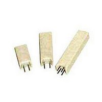
PV, PVH, and PWV resistors are designed for power applications where
space is at a premium. The PV series offers lowest cost for medium
power applications. PVH series are similar except in 4-terminal Kelvin
design (to cancel lead wire effect). PWV bracketed resistors enable
higher power levels and superior performance in applications involving
shock and vibration. The ceramic construction is fireproof and resistant
to moisture & solvents. The internal element is wirewound on lower values,
power film on higher values (depending on options, e.g. opt. P parts are
always WW). If a specific construction is preferred, specify opt.’WW’ for
wirewound, opt.’M’ for power film (not available in all values).
0
0
[
[
1 [
1 [
1 [
B
. 1
. 7
. 8
] 7
] 7
] 7
1 [
1 [
. 2
. 2
[
[
[
[
1 [
1 [
. 1
] 0
] 0
] 0
. 7
. 8
. 9
] 0
] 6
] 9
. 2
. 2
] 7
] 7
] 0
] 0
] 0
] 6
] 9
] 2
Term.W is
RoHS
compliant &
260°C
compatible
] 7
] 7
5 .
5 .
5 .
P/N DESIGNATION:
RCD Type
Options: X, WW, P, M, FF, E, B
(Leave blank if standard)
Resis.Code .05%-1%: 3 signif. figures & multiplier, e.g. R001=.001
R010=.01 , R100=.1
Resis.Code 2%-10%: 2 signif. figures & multiplier, e.g. R001=.001
R01=0.01 , R10=0.1
Tolerance: A=0.05%, B=0.1%, C=0.25%, D=0.5%,
F=1%, G=2%, J=5%(std), K=10%
Packaging: B=bulk (standard)
Optional TC: 10=10ppm, 20=20ppm, 50=50ppm, 101=100ppm,
201=200ppm, etc. (leave blank if standard)
Termination: W= Lead-free, Q= Tin/Lead (leave blank if either is acceptable,
in which case RCD will select based on lowest price and quickest delivery)
±
±
2
8 .
9 .
1
1
1
1
4 .
4 .
4 .
0 .
0 .
0 .
5 .
0 .
3 .
3 .
3
8
8
0
8
0
0
0
0
0
0
±
6
4
8 .
9 .
1
1
2
1
1
2
0
0
0
2
8
8
0
0
0
C
0 .
0 .
2
0 .
5 .
3 .
3 .
C
1 [
1 [
1 [
0
8
5 [
[
2 [
2 [
2 [
3 [
3 [
3 [
. 1
1 [
1 [
1 [
6
0
0
0
2
2
8
8
[
. 3
. 4
. 4
. 1
. 0
. 4
. 5
. 8
. 1
. 5
. 5
2
] 0
] 0
] 0
C
] 0
2 [
2 [
2 [
3 [
5 [
3 [
3 [
] 5
] 7
] 7
] 6
] 3
] 9
] 4
] 6
] 3
] 0
] 0
[
. 1
. 0
. 4
. 5
. 8
. 1
. 5
. 5
2 .
] 6
] 3
Tel: 603
] 3
] 9
] 4
] 6
] 0
] 0
±
1 .
1 .
1 .
1 .
1 .
1 .
±
0 .
0 .
0 .
1 .
1 .
1 .
0 .
9
0 .
9
9
9
9
9
9
6
6
6
0
0
0
0
2 .
D
4
7
7
7
7
7
7
2
0
0
0
0
0
0
±
1 .
1 .
1 .
1 .
1 .
1 .
D
[
PR
0 .
9
[
. 7
[
[
[
[
[
[
[
[
[
[
[
[
[
] 1
] 5
] 5
] 5
] 5
] 5
] 5
9
9
9
9
9
9
. 0
. 1
. 1
. 1
. 2
. 2
. 2
0
] 4
D
4
7
7
7
7
7
7
-
] 5
] 5
] 5
] 5
] 5
669
] 5
] 5
[
, E not to exceed max
[
. 7
[
[
[
[
[
[
0 .
1 .
1 .
1 .
1 .
1 .
1 .
] 1
] 5
] 5
] 5
] 5
] 5
] 5
±
1R0=1
] 4
1R00=1
7
0
0
0
0
2
2
0 .
±
-
2 .
2 .
2 .
0054 Fax: 603
5
0
0
0
0
5
5
2
±
0 .
2 .
2 .
2 .
E
6
7
7
0 .
0 .
0 .
0 .
0 .
0 .
0 .
4
1 [
2 [
2 [
2 [
2 [
3 [
3 [
0 .
0
0
0
6
5
5
5
. [
E
0
2
3
3
3
3
3
3
9 .
5 .
5 .
5 .
5 .
1 .
1 .
0
0
0
] 6
[
[
[
[
8
E
[ 5
1
1
1
1
6
6
. 1
. 6
. 7
. 7
] 1
] 4
] 4
] 4
] 4
] 8
] 8
[
[
[
] 5
] 5
] 5
1 .
. [
. [
. [
. [
. [
. [
. [
] 5
100=10
] 7
] 0
] 0
] 7
] 8
] 8
] 8
] 8
] 9
] 9
S
10R0=10 , 1000=100
] 2
0 .
0 .
0 .
0 .
0 .
0 .
0 .
F
d t
±
3
3
3
3
3
3
3
2 .
2 .
2 .
0 .
0 .
±
2 .
2 .
2 .
0 .
0 .
2
2
2
2
2
2
2
0 .
0 .
0 .
0 .
(
6
9
9
N (
4
4
O
0 .
6
0
0
0
3
(
(
(
(
(
(
(
5
5
5
4
4
4
4
-
8
8
0 .
0 .
0 .
0 .
0 .
0 .
0 .
F
669
0
0
0
o
6
t p
F
0
0
0
0
0
[
[
[
[
. 1
[
[
4
4
4
4
4
4
4
. 6
. 7
. 7
m
" 3
[
[
[
101=100 , 102=1K.
. 1
. 1
. [
B .
[
[
[
[
] 5
] 5
] 5
) 0
) 0
) 0
) 0
) 0
) 0
) 0
] 1
] 1
] 1
] 1
] 9
] 5
] 7
] 5
] 5
-
)
5455
] 2
] 2
)
RESISTORS CAPACITORS COILS DELAY LINES
B
PV10
E
Email:sales@rcdcomponents.com
E
F
A
A
D
C
D
1001=1K
.032x.08” 5-15W, .05x.12” 20-25W (3)
.05” dia.
F
Mounting Layout
.036”
±.005
.040”
(.048 opt.B)
Mounting Layout
- 100 - J B
lead is
terminated
to metal
bracket
Mounting Layout
F
C
C
(dia)
.022”
E
E
B
B
E
B
.125”
.125”
min
min
.125”
min
A
D(3)
48
W
.
Related parts for PV5-103-JBQ
Image
Part Number
Description
Manufacturer
Datasheet
Request
R

Part Number:
Description:
RESISTOR, POWER, 10OHM, 5W, 5%
Manufacturer:
RCD (RESISTORS COILS DELAYLINES)
Datasheet:
Part Number:
Description:
RESISTOR, POWER, 100OHM, 5W, 5%
Manufacturer:
RCD (RESISTORS COILS DELAYLINES)
Datasheet:
Part Number:
Description:
RESISTOR, POWER, 1KOHM, 5W, 5%
Manufacturer:
RCD (RESISTORS COILS DELAYLINES)
Datasheet:
Part Number:
Description:
RESISTOR, POWER, 15OHM, 5W, 5%
Manufacturer:
RCD (RESISTORS COILS DELAYLINES)
Datasheet:
Part Number:
Description:
RESISTOR, POWER, 2KOHM, 5W, 5%
Manufacturer:
RCD (RESISTORS COILS DELAYLINES)
Datasheet:
Part Number:
Description:
RESISTOR, POWER, 2.7KOHM, 5W, 5%
Manufacturer:
RCD (RESISTORS COILS DELAYLINES)
Datasheet:
Part Number:
Description:
RESISTOR, POWER, 33OHM, 5W, 5%
Manufacturer:
RCD (RESISTORS COILS DELAYLINES)
Datasheet:
Part Number:
Description:
RESISTOR, POWER, 4.7KOHM, 5W, 5%
Manufacturer:
RCD (RESISTORS COILS DELAYLINES)
Datasheet:
Part Number:
Description:
RESISTOR, POWER, 4.7OHM, 5W, 5%
Manufacturer:
RCD (RESISTORS COILS DELAYLINES)
Datasheet:

Part Number:
Description:
RESISTOR, POWER, 0.05OHM, 5W, 5%
Manufacturer:
RCD (RESISTORS COILS DELAYLINES)
Datasheet:
Part Number:
Description:
RESISTOR, POWER, 0.2OHM, 5W, 5%
Manufacturer:
RCD (RESISTORS COILS DELAYLINES)
Datasheet:
Part Number:
Description:
RESISTOR, POWER, 0.5OHM, 5W, 5%
Manufacturer:
RCD (RESISTORS COILS DELAYLINES)
Datasheet:

Part Number:
Description:
WIREWOUND RESISTORS
Manufacturer:
RCD (RESISTORS COILS DELAYLINES)

Part Number:
Description:
SWITCH PB SPST 2A 48VDC BLACK
Manufacturer:
E-Switch
Datasheet:

Part Number:
Description:
SWITCH PB SPST 2A 48VDC GREEN
Manufacturer:
E-Switch
Datasheet: