EA KIT160-6MOU01 ELECTRONIC ASSEMBLY, EA KIT160-6MOU01 Datasheet - Page 4
EA KIT160-6MOU01
Manufacturer Part Number
EA KIT160-6MOU01
Description
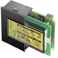
LCD Graphic Display Modules & Accessories Blue/White Contrast RS-232 w/OPT 9/35V
Manufacturer
ELECTRONIC ASSEMBLY
Datasheet
1.EA_KIT160-6MOU01.pdf
(20 pages)
Specifications of EA KIT160-6MOU01
Pixel Density
160 x 80
Module Size (w X H X T)
102 mm x 80 mm x 36 mm
Viewing Area (w X H)
70 mm x 36 mm
Backlighting
LED
Background Color
Blue, White
Operating Temperature Range
- 20 C to + 70 C
Attached Touch Screen
Yes
Product
Graphic LCD Module
Style
LCD Graphic Display
Interface
RS-232
Lead Free Status / RoHS Status
Lead free / RoHS Compliant


EA KIT160-6
SUPPLY 5V / (9-35 V)
In the standard model, the supply voltage of +5V is fed in via screw-type terminal J1. Alternatively, the 5V
can also be fed in at the 10-pin connector J3 (pin 1: 5V; pin 10: 0V) for the RS-232 interface.
In the case of the version for 9V to 35V (EA OPT-9/35V), the power is supplied via J2.
Important: It is imperative that the polarity is correct. Even very brief polarity reversal can damage the
display immediately and irreparably.
RS-232/RS-422 CONNECTION
The operating unit is shipped with an RS-232 interface as standard. The pin assignment of connector
J3 is then as shown in the table on the left. J3 has a grid of 2.54mm. If the operating unit is ordered together
with the EA OPT-RS4224 option, special RS-422 drivers are fitted. The pin assignment in the table on
the right then applies.
BAUD RATES
The baud rate is set in the factory to 9600. You can use the program KITBAUD.EXE (available on
EA DISK240
the new baud rate as a parameter (e.g. KITBAUD 19200). The following baud rates can be set: 1200,
2400, 4800, 9600, 19200, 38400, 57600 and 115200.
Note: solder bridge WP must be open to change baudrate (see page 6 "WRITE PROTECTION").
Please note that the internal data buffer is only 45 bytes. The RTS handshake line must therefore be
queried (+10V level: data can be accepted; -10V level: display is busy). The data format is set
permanently to 8 data bits, 1 stop bit, no parity.
4
Pin
10
1
2
3
4
5
6
7
8
9
Symb
VDD
DCD
GND
DSR
CTS
RTS
DTR
RxD
RS-232C connector J3
TxD
NC
In/Out
Out
Out
In
In
-
-
-
-
-
-
*)
) to configure it. To do this, you have to connect the KIT160 to COM1 or COM2 and pass
+ 5V Supply
Via LB 4 to DTR
Via LB 3 to DTR
Transmit Data
Clear To Send
Receive Data
Request To Send
See Pin 2, Pin 3
Not Connected
0V Ground
Function
Incidentally, the same serial data with 5V
levels and TTL logic is available at the J5
eyelet strip. These levels are suitable for
direct connection to a µC. If these signals
are used, the solder straps LB 10 and LB
11 must be opened (or the four RS422
75176 drivers removed)!
*)
also available at http://www.lcd-module.de/disk/disk240.zip
Pin Symbol In/Out
10
1
2
3
4
5
6
7
8
9
RESET
TxD5
VDD
GND
RTS
CTS
RxD
VU
NC
NC
Pin
10
1
2
3
4
5
6
7
8
9
RS-422 Connector J3
J5 add-on
Data Out + Transmit Data
Data Out - Transmit Data
Out
Out
HS Out +
Data In +
HS Out -
Symbol
Data In -
In
In
In
HS In +
-
-
-
-
-
HS In -
VDD
GND
9..35V supply
+ 5V supply
0V, ground
Transmit data (5V)
Receive data (5V)
Request to send
(5V)
Clear to send (5V)
H: reset
not connected
not connected
handling precautions!
ATTENTION
+5V, Supply
Receive Data
Receive Data
Handshake
Handshake
Handshake
Handshake
0V, Ground
Function
Function
Related parts for EA KIT160-6MOU01
Image
Part Number
Description
Manufacturer
Datasheet
Request
R

Part Number:
Description:
LCD Graphic Display Modules & Accessories Blue/White Contrast RS-232 Snap-In Kit
Manufacturer:
ELECTRONIC ASSEMBLY
Datasheet:

Part Number:
Description:
LCD Graphic Display Modules & Accessories Blue/White Contrast RS-232 Snap-In Kit
Manufacturer:
ELECTRONIC ASSEMBLY
Datasheet:

Part Number:
Description:
Display Modules & Development Tools Starter/Demoboard Windows USB For DOGM
Manufacturer:
ELECTRONIC ASSEMBLY

Part Number:
Description:
Display Modules & Development Tools Starter/Demoboard DOGM/ Windows USB
Manufacturer:
ELECTRONIC ASSEMBLY
Datasheet:

Part Number:
Description:
LCD Character Display Modules 4x20 Yellow/Green RS-232 Interface
Manufacturer:
ELECTRONIC ASSEMBLY
Part Number:
Description:
LCD Character Display Modules 4x20 Blue-White RS-232 Interface
Manufacturer:
ELECTRONIC ASSEMBLY
Part Number:
Description:
LCD Character Display Modules 2x16 Yellow/Green RS-232 Interface
Manufacturer:
ELECTRONIC ASSEMBLY

Part Number:
Description:
LCD Character Display Modules STN(+) Reflective Yel/Grn Background
Manufacturer:
ELECTRONIC ASSEMBLY
Datasheet:

Part Number:
Description:
LCD Character Display Modules STN(-) Transmissive Blue Background
Manufacturer:
ELECTRONIC ASSEMBLY
Datasheet:

Part Number:
Description:
LCD Character Display Modules FSTN(-) Transmissive Black Background
Manufacturer:
ELECTRONIC ASSEMBLY
Datasheet:

Part Number:
Description:
LCD Touch Panels Touchpanel Analog for DOGM128-6
Manufacturer:
ELECTRONIC ASSEMBLY
Datasheet:
Part Number:
Description:
LCD Touch Panels Touchpanel Analog For DOGS102
Manufacturer:
ELECTRONIC ASSEMBLY
Datasheet:
Part Number:
Description:
LCD Touch Panels Touchpanel Analog For DOGXL160
Manufacturer:
ELECTRONIC ASSEMBLY
Datasheet:
Part Number:
Description:
LCD Touch Panels Touchpanel Analog For DOG-L128-6
Manufacturer:
ELECTRONIC ASSEMBLY
Datasheet:

Part Number:
Description:
LED Displays Bezel 017-xx Series 75.0x24.2/ 91.0x36.4
Manufacturer:
ELECTRONIC ASSEMBLY
Datasheet: