S64128LX FC BW-3 Displaytech, S64128LX FC BW-3 Datasheet - Page 20
S64128LX FC BW-3
Manufacturer Part Number
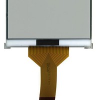
S64128LX FC BW-3
Description
LCD Graphic Display Modules & Accessories 128X64 FSTN With FPC Interface
Manufacturer
Displaytech
Datasheet
1.S64128LX_FC_BW-RGB.pdf
(21 pages)
Specifications of S64128LX FC BW-3
Pixel Density
128 x 64
Fluid Type
FSTN
Module Size (w X H X T)
68.8 mm x 49.2 mm x 8.5 mm
Backlighting
LED White
Operating Temperature Range
- 20 C to + 70 C
Style
White
Display Mode
Positive - Transflective
Lead Free Status / RoHS Status
Lead free / RoHS Compliant


N N N N Precaution for Handing LCD Modules
module or making any alterations or modifications to it.
1.
2.
3.
4.
5.
6.
N N N N Electro-Static Discharge Control
CMOS IC.
1.
2.
3.
4.
5.
6.
N N N N Precaution for soldering to the LCM
1.
in the case of a non-halogen type of flux.) It is recommended that you protect the LCD surface with a cover during soldering to
prevent any damage due to flux spatters.
2.
3.
N N N N Precautions for Operation
1.
2.
3.
4.
5.
6.
Displaytech Ltd
Do not alter, modify or change the shape of the tab on the metal frame.
Do not make extra holes on the printed circuit board, modify its shape or change the positions of components to be attached.
Do not damage or modify the pattern writing on the printed circuit board.
Absolutely do not modify the zebra rubber strip (conductive rubber) or heat seal connector.
Except for soldering the interface, do not make any alterations or modifications with a soldering iron.
Do not drop, bend or twist LCM.
Make certain that you are grounded when handing LCM.
Before remove LCM from its packing case or incorporating it into a set, be sure the module and your body have the same
electric potential.
When soldering the terminal of LCM, make certain the AC power source for the soldering iron does not leak.
When using an electric screwdriver to attach LCM, the screwdriver should be of ground potentiality to minimize as much as
possible any transmission of electromagnetic waves produced sparks coming from the commutator of the motor.
As far as possible make the electric potential of your work clothes and that of the work bench the ground potential.
To reduce the generation of static electricity be careful that the air in the work is not too dried. A relative humidity of
50%-60% is recommended.
Observe the following when soldering lead wire, connector cable and etc. to the LCM.
When soldering the electroluminescent panel and PC board, the panel and board should not be detached more than three
times. This maximum number is determined by the temperature and time conditions mentioned above, though there may be
some variance depending on the temperature of the soldering iron.
When remove the electroluminescent panel from the PC board, be sure the solder has completely melted, the soldered pad on
the PC board could be damaged.
Viewing angle varies with the change of liquid crystal driving voltage (VO). Adjust VO to show the best contrast.
Driving the LCD in the voltage above the limit shortens its life.
Response time is greatly delayed at temperature below the operating temperature range. However, this does not mean the
LCD will be out of the order. It will recover when it returns to the specified temperature range.
If the display area is pushed hard during operation, the display will become abnormal. However, it will return to normal if it
is turned off and then back on.
Condensation on terminals can cause an electrochemical reaction disrupting the terminal circuit. Therefore, it must be used
under the relative condition of 40°C , 50% RH.
When turning the power on, input each signal after the positive/negative voltage becomes stable.
Since LCM has been assembled and adjusted with a high degree of precision, avoid applying excessive shocks to the
Since this module uses a CMOS LSI, the same careful attention should be paid to electrostatic discharge as for an ordinary
If soldering flux is used, be sure to remove any remaining flux after finishing to soldering operation. (This does not apply
•
•
•
Soldering iron temperature : 280°C ± 10°C.
Soldering time : 3-4 sec.
Solder : eutectic solder.
LCD MODULE
S
64128LX-RGB SERIES
Version : 1.0 P 20 of 21
Related parts for S64128LX FC BW-3
Image
Part Number
Description
Manufacturer
Datasheet
Request
R

Part Number:
Description:
LCD Graphic Display Modules & Accessories 128X64 FSTN With FPC Interface
Manufacturer:
Displaytech
Datasheet:

Part Number:
Description:
LCD Graphic Display Modules & Accessories 128X64 FSTN White Backlight
Manufacturer:
Displaytech
Datasheet:
Part Number:
Description:
LCD Graphic Display Modules & Accessories 128X64 FSTN RGB Backlight
Manufacturer:
Displaytech
Datasheet:


Part Number:
Description:
TFT Displays & Accessories 3.3in TFT 320x480 RGB w/touch
Manufacturer:
Displaytech
Datasheet:

Part Number:
Description:
TFT Displays & Accessories 5.7 TFT w/Touch Screen
Manufacturer:
Displaytech
Datasheet:

Part Number:
Description:
TFT Displays & Accessories 4.2in TFT 432x240 RGB w/touch
Manufacturer:
Displaytech
Datasheet:

Part Number:
Description:
TFT Displays & Accessories 7.0 TFT w/Touch Screen
Manufacturer:
Displaytech
Datasheet:
Part Number:
Description:
TFT Displays & Accessories 3.3in TFT 320x480 RGB
Manufacturer:
Displaytech
Datasheet: