HDSP-H573 Avago Technologies US Inc., HDSP-H573 Datasheet

LED Displays Red 626nm CC 5x7 Dot Matrix

HDSP-H573

Manufacturer Part Number
HDSP-H573
Description
LED Displays Red 626nm CC 5x7 Dot Matrix
Manufacturer
Avago Technologies US Inc.
Datasheet

Specifications of HDSP-H573

Number Of Digits
1
Illumination Color
Red
Wavelength
622 nm
Luminous Intensity
3300 ucd
Display Type
5 x 7 Dot Matrix
Lead Free Status / RoHS Status
Lead free / RoHS Compliant
HDSP-H571/H573
5 x 7 General Purpose Dot Matrix Displays
53.2 mm (2.09 inch) Package
Data Sheet
Description
This display comprises 7 rows by 5 columns of 5.0 mm
diameter dots on a pitch of 7.62 mm. The device is
available in common row cathode and common row
anode configurations. The displays come in black face
paint. Each dot has high efficiency red.
Device Selection Guide
HDSP-H571
HDSP-H573
Part Numbering System
HDSP - X X X X
Note:
1. For codes not listed in the figure above, please refer to the respective datasheet or
contact your nearest Avago representative for details.
Description
Common Row Anode
Common Row Cathode
Device Configuration/Color
1: Common Row Anode
3: Common Row Cathode
Character Height/Device Configuration
7: 2.0 to 2.99 inch Height, Common Row Cathode
(for HDSP-Sxxx and Mxxx Series only)
Package Configuration
5: 5 x 7 Dot Matrix
Package Type/Color
Refer to Respective Datasheet
[1]
[1]
[1]
Features
• 5 x 7 Dot matrix
• High Efficiency Red (HER)
• Black face paint
– Dot diameter 5.0 mm
– Dot pitch 7.62 mm
[1]

Related parts for HDSP-H573

HDSP-H573 Summary of contents

Page 1

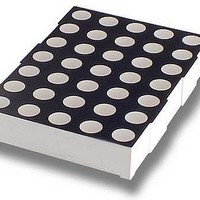
... The displays come in black face paint. Each dot has high efficiency red. Device Selection Guide Description HDSP-H571 Common Row Anode HDSP-H573 Common Row Cathode Part Numbering System HDSP - Device Configuration/Color 1: Common Row Anode 3: Common Row Cathode Character Height/Device Configuration 7: 2 ...

Page 2

... PIN 1 PART NO. YWW = DATE CODE HDSP-H571 YWW COO = COUNTRY OF ORIGIN 2.54 (0.100) (0.600) NOTES: 1. DIMENSIONS IN MILLIMETERS (INCHES). 2. UNLESS OTHERWISE STATED, TOLERANCE IS ± 0.25 mm. 2 5.00 (0.197 INTENSITY BIN 8.60 C00 X (0 ...

Page 3

Internal Circuit Diagram Common Row Anode COLUMN 1 13 PIN ROW PIN NO. FUNCTION 1 ...

Page 4

Internal Circuit Diagram Common Row Cathode COLUMN 1 PIN 13 ROW PIN NO. FUNCTION 1 ...

Page 5

Absolute Maximum Ratings 25˚C A Parameter Power Dissipation per Dot Peak Forward Current per Dot Average Forward Current per Dot Reverse Voltage per Dot Operating Temperature Storage Temperature Wave Soldering Conditions (2 mm [0.079 in.] below Body) ...

Page 6

R = 770°C/W J 100 T – AMBIENT TEMPERATURE – °C A Figure 1. Maximum allowable average current per dot vs. ambient temperature. Contrast Enhancement For information on ...

Related keywords