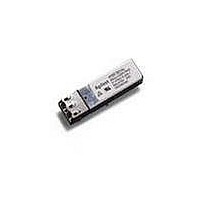
HFBR-5963AL Avago Technologies US Inc., HFBR-5963AL Datasheet - Page 5

HFBR-5963AL
Manufacturer Part Number
HFBR-5963AL
Description
Fiber Optic Transmitters, Receivers, Transceivers OC3/FE 2X5 LC SD LVT TL EXTD TEMP
Manufacturer
Avago Technologies US Inc.
Datasheet
1.HFBR-5963AL.pdf
(13 pages)
Specifications of HFBR-5963AL
Function
Transceivers for ATM, FDDI, Fast Ethernet and SONET OC-3/SDH STM-1 with LC connector.
Product
Transceiver
Data Rate
125 Mbps, 155 Mbps
Wavelength
1300 nm
Maximum Rise Time
3 ns, 2.2 ns
Maximum Fall Time
3 ns, 2.2 ns
Pulse Width Distortion
0.4 ns, 0.3 ns
Maximum Output Current
50 mA
Operating Supply Voltage
2.97 V to 3.63 V
Maximum Operating Temperature
+ 85 C
Minimum Operating Temperature
- 40 C
Package / Case
DIP-10 with Connector
Optical Fiber Type
TX/RX
Data Transfer Rate
155.52MBd
Optical Rise Time
3/2.2ns
Optical Fall Time
3/2.2ns
Jitter
0.4/0.3ns
Operating Temperature Classification
Industrial
Peak Wavelength
1308/1380nm
Package Type
DIP With Connector
Operating Supply Voltage (min)
2.97V
Operating Supply Voltage (typ)
3.3V
Operating Supply Voltage (max)
3.63V
Output Current
50mA
Operating Temp Range
-40C to 85C
Mounting
Snap Fit To Panel
Pin Count
10
For Use With
Multimode Glass
Lead Free Status / RoHS Status
Lead free / RoHS Compliant
Available stocks
Company
Part Number
Manufacturer
Quantity
Price
Company:
Part Number:
HFBR-5963ALZ
Manufacturer:
AVAGO
Quantity:
3 200
Company:
Part Number:
HFBR-5963ALZ
Manufacturer:
Avago Technologies
Quantity:
135
Part Number:
HFBR-5963ALZ
Manufacturer:
AVAGO/安华高
Quantity:
20 000
Board Layout - Hole Pattern
The Avago Technologies transceiver complies with the
circuit board “Common Transceiver Footprint” hole pat-
tern defined in the original multisource announcement
which defined the 2 x 5 package style. This drawing is
reproduced in Figure 6 with the addition of ANSI Y14.5M
compliant dimensioning to be used as a guide in the me-
chanical layout of your circuit board. Figure 6 illustrates
the recommended panel opening and the position of the
circuit board with respect to this panel.
Figure 4. Alternative Termination Circuits
Note:
C1 = C2 = C3 = 10 nF or 100 nF
* Loading R1 is optional.
T X
R X
10
1
9
2
8
3
7
4
5
6
130 Ω
82 Ω
C2
C1
1 µH
1 µH
TRANSCEIVER INPUTS
TERMINATE AT
V CC (+3.3 V)
130 Ω
82 Ω
Z = 50 Ω
Z = 50 Ω
Z = 50 Ω
V CC (+3.3 V)
C3
10 nF
10 µF
Regulatory Compliance
These transceiver products are intended to enable com-
mercial system designers to develop equipment that
complies with the various international regulations
governing certification of Information Technology Equip-
ment. See the Regulatory Compliance Table for details.
Additional information is available from your Avago
Technologies sales representative.
V CC (+3.3 V)
TERMINATE AT DEVICE INPUTS
R1*
4.7KΩ
10 nF
130 Ω
Z = 50 Ω
Z = 50 Ω
82 Ω
V CC (+3.3 V)
130 Ω
82 Ω
TD-
TD+
RD+
RD-
SD
LVTTL
V CC (+3.3 V)
PHY DEVICE
LVPECL
LVPECL
V CC (+3.3 V)


