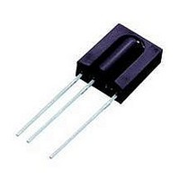
TSOP31256 Vishay, TSOP31256 Datasheet

Infrared Receivers 2.5-5.5V 56kHz 45Deg

TSOP31256

Manufacturer Part Number
TSOP31256
Description
Infrared Receivers 2.5-5.5V 56kHz 45Deg
Manufacturer
Vishay
Datasheet

Specifications of TSOP31256

Carrier Frequency
56 KHz
Supply Current
0.35 mA
Transmission Distance
45 m
Viewing Angle
45 deg
Output Current
5 mA
Operating Voltage
2.5 V to 5.5 V
Maximum Operating Temperature
+ 85 C
Minimum Operating Temperature
- 25 C
Transmission Range
45m
Directivity
45°
Supply Voltage Range
2.5V To 5.5V
Opto Case Style
Through Hole
Operating Temperature Range
-25°C To +85°C
Lead Free Status / RoHS Status
Lead free / RoHS Compliant

Available stocks

Company
Part Number
Manufacturer
Quantity
Price
Part Number:
TSOP31256
Quantity:
62
Part Number:
TSOP31256
Manufacturer:
ROHM
Quantity:
7 530
TSOP312.., TSOP314..
Vishay Semiconductors
MECHANICAL DATA
Pinning:
1 = GND, 2 = V
BLOCK DIAGRAM
** Please see document “Vishay Material Category Policy”:
www.vishay.com
1
PARTS TABLE
CARRIER FREQUENCY
30 kHz
33 kHz
36 kHz
38 kHz
40 kHz
56 kHz
16832
PIN
Input
1
2
S
IR Receiver Modules for Remote Control Systems
, 3 = OUT
3
AGC
Control circuit
Band
pass
STANDARD APPLICATIONS (AGC2/AGC8)
Demo-
dulator
94 8691
30 kΩ
TSOP31230
TSOP31233
TSOP31236
TSOP31238
TSOP31240
TSOP31256
www.vishay.com/doc?99902
OUT
GND
V
3
2
1
S
FEATURES
• Very low supply current
• Photo detector and preamplifier in one
• Internal filter for PCM frequency
• Improved shielding against EMI
• Supply voltage: 2.5 V to 5.5 V
• Improved immunity against ambient light
• Insensitive to supply voltage ripple and noise
• Compliant to RoHS Directive 2002/95/EC and in
DESCRIPTION
The TSOP312.., TSOP314.. series are miniaturized receivers
for infrared remote control systems. A PIN diode and a
preamplifier are assembled on a lead frame, the epoxy
package acts as an IR filter.
The demodulated output signal can be directly decoded by
a microprocessor. The TSOP312.. is compatible with all
common IR remote control data formats. The TSOP314.. is
optimized to suppress almost all spurious pulses from
energy saving fluorescent lamps but will also suppress
some data signals.
This component has not been qualified according to
automotive specifications.
APPLICATION CIRCUIT
package
accordance to WEEE 2002/96/EC
17170_5
R
Components should be in the range of 33 Ω < R
C
Transmitter
TSALxxxx
1
1
and C
> 0.1 µF.
with
1
are recommended for protection against EOS.
VERY NOISY ENVIRONMENTS (AGC4)
IR receiver
TSOP31430
TSOP31433
TSOP31436
TSOP31438
TSOP31440
TSOP31456
GND
V
OUT
S
Document Number: 81745
C
R
1
1
Rev. 1.4, 04-Feb-11
V
1
< 1 kΩ,
O
µC
GND
+ V
S

Related parts for TSOP31256

TSOP31256 Summary of contents

Page 1

... This component has not been qualified according to automotive specifications. TSOP31230 TSOP31233 TSOP31236 TSOP31238 TSOP31240 TSOP31256 APPLICATION CIRCUIT 17170_5 2 Transmitter V S TSALxxxx 30 kΩ 3 ...

Page 2

... E e max. test signal see fig. 1  1/2 distance = 25 °C, unless otherwise specified) amb , ms 16110 t Fig Pulse Length and Sensitivity in Dark Ambient TSOP312.., TSOP314.. Vishay Semiconductors VALUE - 100 stg - tot 260 sd MIN. TYP. MAX. 0.27 0.35 0.45 ...

Page 3

... TSOP312.., TSOP314.. Vishay Semiconductors Optical Test Signal E e 600 µs 600 µ Output Signal, (see fig Fig Output Function 0.8 0.7 0.6 0.5 0.4 0.3 0.2 λ = 950 nm, 0.1 Optical Test Signal, Fig 0 100 20759 E - Irradiance (mW/m e Fig Output Pulse Diagram 1 ...

Page 4

... Fig Relative Spectral Sensitivity vs. Wavelength Document Number: 81745 Rev. 1.4, 04-Feb-11 IR Receiver Modules for Remote Control Systems TSOP312.. 80 100 120 95 11340p2 11339p2 1050 1150 TSOP312.., TSOP314.. Vishay Semiconductors 0 ° 10 ° 20 ° 1.0 0.9 0.8 0.7 0.6 0.4 0.2 0 0.2 0 Relative Transmission Distance rel Fig Horizontal Directivity 0 ° ...

Page 5

... TSOP312.., TSOP314.. Vishay Semiconductors SUITABLE DATA FORMAT The TSOP312.., TSOP314.. series are designed to suppress spurious output pulses due to noise or disturbance signals. Data and disturbance signals can be distinguished by the devices according to carrier frequency, burst length and envelope duty cycle. The data signal should be close to the band-pass center frequency (e ...

Page 6

... Rev. 1.4, 04-Feb-11 IR Receiver Modules for Remote Control Systems 10 ± 0.3 Center of sensitive area Area not plane + 0.15 0 2.54 = 7.62 nom. technical drawings according to DIN specifications TSOP312.., TSOP314.. Vishay Semiconductors + 0.10 0.4 - 0.05 1.4 ± 0.3 4 ± 0.3 5.8 ± 0.3 www.vishay.com 6 ...

Page 7

... Vishay product could result in personal injury or death. Customers using or selling Vishay products not expressly indicated for use in such applications their own risk and agree to fully indemnify and hold Vishay and its distributors harmless from and against any and all claims, liabilities, expenses and damages arising or resulting in connection with such use or sale, including attorneys fees, even if such claim alleges that Vishay or its distributor was negligent regarding the design or manufacture of the part ...

Related keywords