LRTBG6SG-T1V1+U1AA-25+R1T OSRAM Opto Semiconductors Inc, LRTBG6SG-T1V1+U1AA-25+R1T Datasheet
LRTBG6SG-T1V1+U1AA-25+R1T
Specifications of LRTBG6SG-T1V1+U1AA-25+R1T


Related parts for LRTBG6SG-T1V1+U1AA-25+R1T


LRTBG6SG-T1V1+U1AA-25+R1T Summary of contents
Page 1
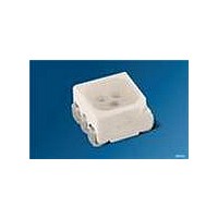
MULTILED Enhanced optical Power LED (ThinFilm / ThinGaN) Lead (Pb) Free Product - RoHS Compliant LRTB G6SG Vorläufige Daten nach OS-PCN-2006-006-A1-B / Preliminary Data acc. to OS-PCN-2006-006-A1-B Besondere Merkmale • Gehäusetyp: weißes P-LCC-6 Gehäuse, (RGB-Displays) und diffusem Silikon Verguss ...
Page 2
Bestellinformation Ordering Information Typ Emissionsfarbe Type Color of Emission LRTB G6SG red true green blue Bestellinformation Ordering Information Typ Type LRTB G6SG-U4AA-1+V2B4-25+S1U2-35 LRTB G6SG-U4AA-1+V2B4-25+S1V1-68 Anm: Die oben genannten Typbezeichnungen umfassen die bestellbaren Selektionen. Diese bestehen aus wenigen Helligkeitsgruppen (siehe Seite ...
Page 3
Grenzwerte Maximum Ratings Bezeichnung Parameter Betriebstemperatur Operating temperature range Lagertemperatur Storage temperature range Sperrschichttemperatur Junction temperature Durchlassstrom Forward current T ( =25°C) A Stoßstrom Surge current μ 0.005, =25° Seite ...
Page 4
Kennwerte Characteristics ( °C) A Bezeichnung Parameter Wellenlänge des emittierten Lichtes Wavelength at peak emission Seite 23 Dominantwellenlänge 4) page 23 Dominant wavelength Spektrale Bandbreite bei ...
Page 5
Seite 23 Farbortgruppen Chromaticity Coordinate Groups 0.9 0.8 y 0.7 0.6 0.5 0.4 0.3 0.2 0.1 0 Gruppe Cx Group 3 0.112 0.150 0.182 0.153 4 0.137 0.169 0.205 0.181 5 0.164 0.190 0.230 0.212 6 0.194 0.216 ...
Page 6
Floating Bins U4 = 502 ... 631 [mcd 560 ... 710 [mcd 631... 799 [mcd] Floating Bins V2 = 900 ... 1120 [mcd 1004... 1252 [mcd 1120 ... 1400 [mcd] 2009-10-14 red ...
Page 7
Floating Bins S1 = 180 ... 224 [mcd 201 ... 250 [mcd 224 ... 280 [mcd 250... 320 2009-10-14 blue [mcd 280 ... 355 [mcd 315 ... 400 [mcd] T2 ...
Page 8
Wellenlängengruppen (Dominantwellenlänge) Wavelength Groups (Dominant Wavelength) Gruppe true green Group min. max. 3 518.5 526.5 4 523.5 531.5 5 528.5 536.5 6 533.5 541.5 Gruppenbezeichnung auf Etikett Group Name on Label Beispiel: T2-1+U2-4+R2-7 Example: T2-1+U2-4+R2-7 Helligkeits- Wellenlänge gruppe (keine Gruppierung) ...
Page 9
Relative spektrale Emission Relative Spectral Emission λ spektrale Augenempfindlichkeit / Standard eye response curve λ ° rel A F 100 % I rel 80 60 ...
Page 10
Seite 23 Durchlassstrom 6) page 23 Forward Current °C; red 1.7 1.9 2.1 6) Seite 23 ...
Page 11
Seite 23 Dominante Wellenlänge 6) page 23 Dominant Wavelength , λ blue = °C dom F A 466 nm λ dom 464 462 460 458 456 454 452 ...
Page 12
Maximal zulässiger Durchlassstrom rot Max. Permissible Forward Current red chip temp. ambient temp. solder point S 0 ...
Page 13
Maximal zulässiger Durchlassstrom blau Max. Permissible Forward Current blue chip temp. ambient A T temp. solder point ...
Page 14
Zulässige Impulsbelastbarkeit Permissible Pulse Handling Capability Duty cycle D = parameter red (1 Chip on 0. 0.10 0.2 0.5 0. 0.06 0.005 0.01 0.02 0.04 ...
Page 15
Zulässige Impulsbelastbarkeit Permissible Pulse Handling Capability Duty cycle D = parameter true green (1 Chip on 0. 0.30 0.25 0.20 0.15 0.10 0.05 ...
Page 16
Zulässige Impulsbelastbarkeit Permissible Pulse Handling Capability Duty cycle D = parameter blue (1 Chip on 0. 0.30 0.25 0.20 0.15 0.10 0.05 0 ...
Page 17
Seite 23 Maßzeichnung 8) page 23 Package Outlines C1 Package marking Gewicht / Approx. weight: Gurtung / Polarität und Lage Method of Taping / Polarity and Orientation 1.5 (0.059) 4 (0.157) 3.5 (0.138) 2009-10-14 3.5 (0.138) 3.1 (0.122) 1.6 ...
Page 18
Empfohlenes Lötpaddesign Recommended Solder Pad Gehäusemarkierung Package marking per anode pad for improved heat dissipation Empfohlenes Platinendesign für cluster mit 6-lead TOPLED in Serienschaltung Recommended PCB-Design for cluster with 6-lead TOPLED in ...
Page 19
Lötbedingungen Soldering Conditions Reflow Lötprofil für bleifreies Löten Reflow Soldering Profile for lead free soldering 300 ˚C 255 ˚C 250 T 240 ˚C 217 ˚C 200 150 100 Ramp K/s (max) 25 ˚ 2009-10-14 Vorbehandlung ...
Page 20
Barcode-Produkt-Etikett (BPL) Barcode-Product-Label (BPL) OSRAM Opto Semiconductors (6P) BATCH NO: Batch Number Bar Code (1T) LOT NO: (X) PROD NO: Product Code Gurtverpackung Tape and Reel Direction of unreeling Tape dimensions in mm (inch ...
Page 21
Trockenverpackung und Materialien Dry Packing Process and Materials Anm.: Feuchteempfindliche Produkte sind verpackt in einem Trockenbeutel zusammen mit einem Trockenmittel und einer Feuchteindikatorkarte Bezüglich Trockenverpackung finden Sie weitere Hinweise im Internet und in unserem Short Form Catalog im Kapitel “Gurtung ...
Page 22
Revision History: 2009-10-14 Previous Version: 2007-08-08 Page Subjects (major changes since last revision) 1 acc. to OS-PCN-2006-006-A 9 Relative Luminous Intensity 4 acc. to OS-PCN-2006-006-A1 7,8 new ordering code new ordering codes Attention please! The ...
Page 23
Fußnoten: 1) Helligkeitswerte werden Stromeinprägedauer von Genauigkeit von ± 11% ermittelt. 2) Die LED kann kurzzeitig in Sperrichtung betrieben werden ergibt sich bei Montage auf PC-Board FR 4 thJA (Padgröße ≥ Pad) 4) Wellenlängen ...