CBT-90-W65S-C11-GP102 Luminus Devices, CBT-90-W65S-C11-GP102 Datasheet - Page 6
CBT-90-W65S-C11-GP102
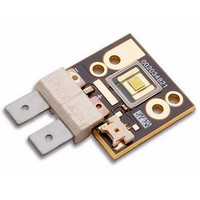
Manufacturer Part Number
CBT-90-W65S-C11-GP102
Description
LED Arrays, Modules and Light Bars White 6500K 1200lm @ 9A
Manufacturer
Luminus Devices
Datasheet
1.CBT-90-W65S-C11-GP102.pdf
(10 pages)
Specifications of CBT-90-W65S-C11-GP102
Product
LED Modules
Illumination Color
Cool White
Color Temperature
6500 K
Supply Voltage
3.6 V
Led Size
3 mm x 3 mm
Supply Current
9 A
Lead Free Status / RoHS Status
Lead free / RoHS Compliant
Available stocks
Company
Part Number
Manufacturer
Quantity
Price
Company:

Part Number:
CBT-90-W65S-C11-GP102
Manufacturer:
Luminus Devices
Quantity:
135


Optical and Electrical Characteristics at TrueTemp
Common Characteristics
Absolute Maximum Ratings
Note 1:
Note 2:
Note 3:
Note 4:
Note 5:
Note 6:
Note 7:
Note 8:
Note 9:
Drive Condition
Parameter
Current Density
Forward Voltage
Emitting Area
Emitting Area Dimensions
Color Temperature
Color Rendering Index
Dynamic Resistance
Forward Voltage Temperature Coefficient
Maximum Current
Maximum Junction Temperature
Storage Temperature Range
All ratings are based on operation with a constant heat sink temperature T
Listed drive conditions are typical for common applications. PhlatLight® CBT-90 devices can be driven at currents ranging from <1 A
to 13.5 A and at duty cycles ranging from 1% to 100%. Drive current and duty cycle should be adjusted as necessary to maintain the
junction temperature desired to meet application lifetime requirements.
Unless otherwise noted, values listed are typical.
CCT value based off of CIE measurement. CIE measurement uncertainty for white devices is estimated to be +/- 0.01.
Forward voltage temperature coefficient at current density of 1.0 A/mm
Luminus PhlatLight CBT-90-W LEDs are designed for operation to an absolute maximum forward drive current density of 2.0 A/mm
Product lifetime data is specified at recommended forward drive currents. Sustained operation at absolute maximum currents will
result in a reduction of device lifetime compared to recommended forward drive currents. Actual device lifetimes will also depend on
junction temperature. Refer to the lifetime derating curves for further information. In pulsed operation, rise time from 10-90% of
forward current should be larger than 0.5 microseconds.
Lifetime dependent on LED junction temperature. Input power and thermal system must be properly managed to ensure lifetime. See
charts on pg 6 for further information.
Special design considerations must be observed for operation under 1 A. Please contact Luminus for further information.
Caution must be taken not to stare at the light emitted from these LEDs. Under special circumstances, the high intensity could dam-
age the eye.
CBT-90 - Product Datasheet
2
6
4
7
5
Symbol
Symbol
V
T
V
V
Ω
CCT
F,max
jtrans
F,min
F,typ
R
dyn
j
a
Indicated Current
Cool White
Typ. Values at
Continuous
1
3.2A
0.35
3.2
(T
heat sink
2
. Contact Luminus for value at other drive conditions.
3
hs
=40ºC. See Thermal Resistance section for T
= 40 ºC)
Test Currents
© 2011 Luminus Devices, Inc. - All Rights Reserved
Continuous
Values at
-40/+100
Values
9.0 A
6,500
0.050
-5.47
3 x 3
>70
150
1.0
3.3
3.6
4.3
9.0
18
Indicated Current
Typ. Values at
Continuous
13.5 A
1.5
3.7
hs
definition.
mm
A/mm
mV/ºC
mm
Unit
Unit
2
ºC
ºC
Ω
V
K
A
.
Page 6
x
mm
2
2
Related parts for CBT-90-W65S-C11-GP102
Image
Part Number
Description
Manufacturer
Datasheet
Request
R

Part Number:
Description:
LED Arrays, Modules and Light Bars White 6500K 1200lm @ 9A
Manufacturer:
Luminus Devices
Part Number:
Description:
LED Arrays, Modules and Light Bars White 6500K 1450lm @ 9A
Manufacturer:
Luminus Devices
Part Number:
Description:
LED Arrays, Modules and Light Bars White 6500K 1450lm @ 9A
Manufacturer:
Luminus Devices
Part Number:
Description:
LED Arrays, Modules and Light Bars White 6500K 1750lm @ 9A
Manufacturer:
Luminus Devices
Part Number:
Description:
LED Arrays, Modules and Light Bars White 6500K 1750lm @ 9A
Manufacturer:
Luminus Devices
Part Number:
Description:
LED Arrays, Modules and Light Bars White 6500K 1750lm @ 9A
Manufacturer:
Luminus Devices
Part Number:
Description:
LED Arrays, Modules and Light Bars White 6500K 1200lm @ 9A
Manufacturer:
Luminus Devices
Datasheet:
Part Number:
Description:
LED Arrays, Modules and Light Bars White 6500K 1450lm @ 9A
Manufacturer:
Luminus Devices
Datasheet:

Part Number:
Description:
LED Arrays, Modules and Light Bars White 6500K 1040lm @ 9A
Manufacturer:
Luminus Devices
Part Number:
Description:
LED Arrays, Modules and Light Bars White 6500K 1380lm @ 9A
Manufacturer:
Luminus Devices
Part Number:
Description:
LED Arrays, Modules and Light Bars White 6500K 1040lm @ 9A
Manufacturer:
Luminus Devices
Part Number:
Description:
LED Arrays, Modules and Light Bars White 6500K 1200lm @ 9A
Manufacturer:
Luminus Devices
Part Number:
Description:
LED Arrays, Modules and Light Bars White 6500K 1380lm @ 9A
Manufacturer:
Luminus Devices
Part Number:
Description:
LED Arrays, Modules and Light Bars White 6500K 1380lm @ 9A
Manufacturer:
Luminus Devices
Part Number:
Description:
LED Arrays, Modules and Light Bars White 6500K 1040lm @ 9A
Manufacturer:
Luminus Devices