KIT34844AEPEVBE Freescale Semiconductor, KIT34844AEPEVBE Datasheet - Page 22
KIT34844AEPEVBE
Manufacturer Part Number
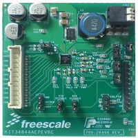
KIT34844AEPEVBE
Description
LED Lighting Development Kits IC, 10 CHANNEL LED BACKLIGHT
Manufacturer
Freescale Semiconductor
Datasheet
1.MC34844AEP.pdf
(62 pages)
Specifications of KIT34844AEPEVBE
Supply Voltage
12 V
Supply Current
2 uA
For Use With/related Products
34844A
Lead Free Status / RoHS Status
Lead free / RoHS Compliant


Configuration, refer
and NIN pins are enabled to scale the current capability per
string and may be disable by setting 2.2 V in the
corresponding pin.
configuration, the PWM signal applied to PWM pin will be in
charge of controlling the LED dimming and a second signal
will enable or disable the chip through the EN pin.
configuration the PWM pin should be tied to SDA pin. The
device (1110110), the control unit needs to follow a specific data transfer format which is shown in
following order:
I
• START: this condition occurs when SDA changes from
• ACKNOWLEDGE: The acknowledge clock pulse is
• The transmitter releases the SDA line (HIGH) during the
Analog Integrated Circuit Device Data
Freescale Semiconductor
2
C
1. START condition
2. The 34844 device address and Write instruction (R/W
3. First data pack, it corresponds to the 34844 Register
4. Second data pack, it corresponds to the value that
5. STOP condition
During manual mode, all internal Registers are in Default
Also in this mode, the device can be enabled as follows:
+ EN pin + PWM signal (Two Signals): In this
+ PWM Signal tied to SDA pin (Just ONE signal): In this
The 34844 is a unidirectional device that can only be written by an external control unit. Since the device is a 7 bit address
For a complete data transfer, please use this format in the
HIGH to LOW while SCK is HIGH.
generated by the Master (Control Unit).
acknowledge clock pulse.
variables description:
= 0)
that needs to be written. (refer to
should be written to that register. (refer to
Table
7, under this configuration the PIN
Table
Figure 8. A Complete Data Transfer
)
Table
I
2
Figure 21
C BUS SPECIFICATION
)
PWM signal applied to PWM pin will be in charge of
controlling LED dimming and enable the device every time
the PWM is active. For this configuration EN pin should be
LOW.
POWER DOWN MODE
device enters automatically into power down mode. When in
power down, the supply current is reduced below 2.0 μA
when there is no I
interface is enabled.
• Bits in the first byte: The first seven bits of the first bite
• STOP: this condition occurs when SDA changes from
please refer to the following link:
9398/39340011.pdf
If the input voltage falls below the UVLO threshold, the
The receiver (34844) must pull down the SDA line during
this acknowledge pulse to indicate that the data was
correctly written.
make up the slave address. The eighth bit is the LSB (least
significant bit), which determines the direction of the
message (Write = 0)
For the 34844 device, when an address is sent, each of the
devices in a system compares the first seven bits after the
START condition with its address. If they match, the
device considers itself addressed by the control unit as a
slave-receiver.
LOW to HIGH while SCK is HIGH
For more information about “I
http://www.nxp.com/acrobat_download/literature/
2
C activity, and it rises up when I
FUNCTIONAL DEVICE OPERATION
Figure
2
C BUS SPECIFICATION”
I2C BUS SPECIFICATION
8.
2
C
34844
22
Related parts for KIT34844AEPEVBE
Image
Part Number
Description
Manufacturer
Datasheet
Request
R

Part Number:
Description:
Manufacturer:
Freescale Semiconductor, Inc
Datasheet:
Part Number:
Description:
Manufacturer:
Freescale Semiconductor, Inc
Datasheet:
Part Number:
Description:
Manufacturer:
Freescale Semiconductor, Inc
Datasheet:
Part Number:
Description:
Manufacturer:
Freescale Semiconductor, Inc
Datasheet:
Part Number:
Description:
Manufacturer:
Freescale Semiconductor, Inc
Datasheet:
Part Number:
Description:
Manufacturer:
Freescale Semiconductor, Inc
Datasheet:
Part Number:
Description:
Manufacturer:
Freescale Semiconductor, Inc
Datasheet:
Part Number:
Description:
Manufacturer:
Freescale Semiconductor, Inc
Datasheet:
Part Number:
Description:
Manufacturer:
Freescale Semiconductor, Inc
Datasheet:
Part Number:
Description:
Manufacturer:
Freescale Semiconductor, Inc
Datasheet:
Part Number:
Description:
Manufacturer:
Freescale Semiconductor, Inc
Datasheet:
Part Number:
Description:
Manufacturer:
Freescale Semiconductor, Inc
Datasheet:
Part Number:
Description:
Manufacturer:
Freescale Semiconductor, Inc
Datasheet:
Part Number:
Description:
Manufacturer:
Freescale Semiconductor, Inc
Datasheet:
Part Number:
Description:
Manufacturer:
Freescale Semiconductor, Inc
Datasheet: