E3G-R13 Omron, E3G-R13 Datasheet
E3G-R13
Specifications of E3G-R13


Related parts for E3G-R13


E3G-R13 Summary of contents
Page 1
... E39-R2 1 mm)* E39-R1 1 (Refer to Dimensions on page 12.) Minimum order Applicable model E3G-MR19(T) 1 E3G-ML79(T) CSM_E3G_DS_E_3_1 Red light Infrared light Model Timer NPN/PNP function Relay output selector E3G-R13 2M --- --- E3G-R17 E3G-MR19 --- Yes E3G-MR19T E3G-L73 2M --- --- E3G-L77 E3G-ML79 --- Yes E3G-ML79T Remarks Provided with the E3G-R1@/MR19(T). --- Remarks Provided with rubber bushing and cap for pullout prevention in vertical direction ...
Page 2
... Straight Standard L-shaped Note: Refer to Introduction to Sensor I/O Connectors for details. Quantity Applicable model 1 E3G-R1@ E3G-L7@ 1 Rear-mounting use 1 Cable pulled out in the downward direction E3G-MR19(T) E3G-ML79(T) 1 Cable type Model 2 m XS2F-D421-DC0-A Three XS2F-D421-GC0-A conductor 2 m XS2F-D422-DC0-A type 5 m XS2F-D422-GC0-A E3G Remarks --- --- 2 ...
Page 3
... Ratings and Specifications Sensing method Retro-reflective (with MSR function) Item Model E3G-R13 E3G-R17 Sensing distance 10 m (500 mm)*1 (when using E39-R2) Setting distance Standard Opaque: 80-mm dia. min. sensing object Differential travel (typical) Directional angle Sensor: 1° to 5° Reflectivity char- ...
Page 4
... Engineering Data (Typical) E3G-R/MR Retro-reflective Models Excess Gain vs. Set Distance 500 E39-R2 Reflector 100 10 Operating level 1 0 Distance (m) E3G-L/ML Distance-setting Models Spot Diameter vs. Sensing Distance 120 Horizontal Vertical 100 0.5 1 1.5 2 2.5 Distance (m) Sensing Object Size vs. Setting Distance 3 White paper Distance setting: 0.5, 1, and 2 m Black paper 2 ...
Page 5
... Reset PNP Output Operation Model Timing charts mode Incident light No incident light Operation indicator Light-ON (orange) Output transistor Operate Load (relay) E3G-R13 Reset E3G-R17 E3G-L73 E3G-L77 Incident light No incident light Operation indicator Dark-ON (orange) Output transistor Operate Load (relay) Reset Sensing Distance vs. Sensing Object Material (at 1-m Setting Distance) 1 ...
Page 6
... Wire color Classifi- Wire Connector cation color pin No. Brown Blue Brown 1 Black --- 2 DC Blue 3 Black 4 Note: Pin 2 is not used. E3G Output circuit Contact output (G6C Relay built in Photo 240 VAC or electric Power 12 to 240 VDC Sensor supply main (no polarity restriction) ...
Page 7
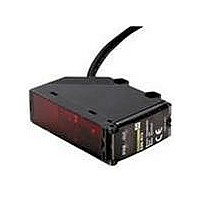
... Nomenclature Retro-reflective E3G-R13 (Pre-wired Model) E3G-R17 (Standard Connector Model) Stability indicator (Green) Sensitivity adjuster E3G-MR19 (Terminal Block Model) E3G-MR19T (Terminal Block Model with Timer) Sensitivity adjuster ON-delay adjuster * OFF-delay adjuster * * The ON- or OFF-delay adjuster is not available with the E3G-MR19. Distance-setting E3G-L73 (Pre-wired Model) ...
Page 8
... E3G-MR19(T). ● Wiring The tensile strength of the cable during operation should not exceed the values shown below. Tensile strength Model (torque) E3G-R13 50 N max. E3G-MR19(T) E3G-R17 10 N max. ● Adjusting Indicators • The following illustration indicates the operating levels of the E3G. ...
Page 9
... The E3G has a built-in function to protect the E3G from load shortcircuiting. If load shortcircuiting results, the output will be turned OFF. In that case, check the wiring and turn ON the E3G again so that Terminal protection cover the short-circuit protection circuit will be reset. This function will operate if the output current flow is at least 2 ...
Page 10
... PF1/2 conduit: JIS B 0202 E3G (Unit: mm) Standard Connector Model E3G-R17 Note: All dimensions other than the ones specified below are the same as the corresponding dimensions of E3G-R13 M12 Connector 10.5 dia. 43 *The ON- or OFF-delay adjuster is not available with the E3G-MR19. Mounting Holes ...
Page 11
... Standard Connector Model E3G-L77 Note: All dimensions other than the ones specified below are the same as the corresponding dimensions of the E3G-L73 M12 Connector 10.5 dia. 43 *The ON- or OFF-delay adjuster is not available with the E3G-ML79. Mounting Holes Two, 4.5-dia. mounting holes ...
Page 12
... Refer to page 9 for the mounting method of the product. Reflectors Refer to E39-L/F39-L/E39-S/E39-R for details. Mounting Brackets Refer to E39-L/F39-L/E39-S/E39-R for details. Sensor I/O Connectors Refer to Introduction to Sensor I/O Connectors for details. Terminal Protection Cover for Side-pullout Cable (Example: E3G-MR19) M2.6 61 E3G M2.6 Hexagonal nut (Diagonal: 22) Applicable cable dia ...
Page 13
... Please read and understand this catalog before purchasing the products. Please consult your OMRON representative if you have any questions or comments. WARRANTY OMRON's exclusive warranty is that the products are free from defects in materials and workmanship for a period of one year (or other period if specified) from date of sale by OMRON. OMRON MAKES NO WARRANTY OR REPRESENTATION, EXPRESS OR IMPLIED, REGARDING NON-INFRINGEMENT, MERCHANTABILITY, OR FITNESS FOR PARTICULAR PURPOSE OF THE PRODUCTS ...