E3Z-B62 Omron, E3Z-B62 Datasheet - Page 3
E3Z-B62
Manufacturer Part Number
E3Z-B62
Description
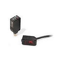
Photoelectric Sensors - Industrial NPN PRE-WIRED
Manufacturer
Omron
Series
E3Z-Br
Specifications of E3Z-B62
Sensing Distance
78.740" (2m)
Sensing Method
Retroreflective
Sensing Object
Mirror
Output Configuration
NPN - Dark-ON/Light-ON - Selectable
Sensing Light
Red
Mounting Type
Bracket Mount
Current - Supply
30mA
Voltage - Supply
12 V ~ 24 V
Package / Case
Module, Pre-Wired
Features
Transparent Object Detection
Lead Free Status / RoHS Status
Lead free / RoHS Compliant
Available stocks
Company
Part Number
Manufacturer
Quantity
Price
Company:

Part Number:
E3Z-B62
Manufacturer:
OMRON
Quantity:
1 000


I/O Circuit Diagrams
NPN Output
PNP Output
Plugs (Sensor I/O Connectors)
3
4
E3Z-B61
E3Z-B62
E3Z-B66
E3Z-B67
E3Z-B81
E3Z-B82
E3Z-B86
E3Z-B87
2
Model
Model
1
1
2
3
4
Operation
Operation
XS3F-M421-402-A
XS3F-M421-405-A
XS3F-M422-402-A
XS3F-M422-405-A
Light-ON
Light-ON
Dark-ON
Dark-ON
mode
mode
Operation
indicator
(orange)
Output
transistor
Load
(e.g., relay)
Operation
indicator
(orange)
Output
transistor
Load
(e.g., relay)
Operation
indicator
(orange)
Output
transistor
Load
(e.g., relay)
Load
(e.g., relay)
No incident light
Output
transistor
Operation
indicator
(orange)
No incident light
(Between brown and black leads)
No incident light
(Between brown and black leads)
No incident light
Incident light
(Between blue and black leads)
Incident light
Incident light
(Between blue and black leads)
Incident light
Wire color
Timing charts
Timing charts
Operate
Brown
White
Blue
Black
Operate
Operate
Operate
Reset
Reset
Reset
OFF
OFF
Reset
OFF
OFF
ON
ON
OFF
OFF
OFF
OFF
ON
ON
ON
ON
ON
ON
E39-ECON@M
E39-ECONW@M
(LIGHT ON)
(LIGHT ON)
(DARK ON)
(DARK ON)
Operation
Operation
selector
selector
D side
D side
L side
L side
Retro-reflective Model
Retro-reflective Model
Connector Pin Arrangement
Operation
indicator
(orange)
Operation
indicator
(orange)
Pin 2 is not used.
Note: Pin 2 is not used.
Connector Pin Arrangement
Classifi-
cation
1
DC
2
Pin 2 is not used.
4
3
Stability
indicator
(green)
Stability
indicator
(green)
1
2
Photo-
electric
Sensor
Main
Circuit
Photo-
electric
Sensor
Main
Circuit
Brown
4
White
color
Black
Wire
Blue
3
Output circuit
Output circuit
(Control output)
(Control output)
e-CON Connector Pin Arrangement
Connector
pin No.
1
2
3
4
Z
Z
D
D
1
2
3
4
1
4
3
1
4
3
Brown
Black
Blue
Brown
Black
Blue
Power supply (0 V)
Power supply (+V)
100mA
max.
100mA
max.
Application
Output
12 to 24 VDC
E3Z-B
12 to 24 VDC
---
(relay)
Load
(relay)
Load
0 V
0 V
3
Related parts for E3Z-B62
Image
Part Number
Description
Manufacturer
Datasheet
Request
R

Part Number:
Description:
30M T/B NPN 4 PIN M8 CONN
Manufacturer:
Omron
Datasheet:
Part Number:
Description:
30M T/B PNP 4 PIN M8 CONN
Manufacturer:
Omron
Datasheet:

Part Number:
Description:
Photoelectric Sensors - Industrial PNP M8 CONNECTOR
Manufacturer:
Omron
Datasheet:

Part Number:
Description:
Photoelectric Sensors - Industrial NPN PET BOTTLE PRE-WIRED
Manufacturer:
Omron
Datasheet:
Part Number:
Description:
Photoelectric Sensors - Industrial NPN M8 CONNECTOR
Manufacturer:
Omron
Datasheet:
Part Number:
Description:
Photoelectric Sensors - Industrial PNP PRE-WIRED
Manufacturer:
Omron
Datasheet:
Part Number:
Description:
Photoelectric Sensors - Industrial E3Z T/B 0.3M M12 conn
Manufacturer:
Omron
Datasheet:
Part Number:
Description:
NPN PRE-WIRED
Manufacturer:
Omron
Datasheet:
Part Number:
Description:
PNP PRE-WIRED
Manufacturer:
Omron
Datasheet:
Part Number:
Description:
PNP M8 CONNECTOR
Manufacturer:
Omron
Datasheet:

Part Number:
Description:
G6S-2GLow Signal Relay
Manufacturer:
Omron Corporation
Datasheet:
Part Number:
Description:
Compact, Low-cost, SSR Switching 5 to 20 A
Manufacturer:
Omron Corporation
Datasheet:
Part Number:
Description:
Manufacturer:
Omron Corporation
Datasheet: