E3F2-D1C4-M 2M Omron, E3F2-D1C4-M 2M Datasheet - Page 26
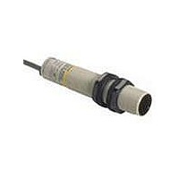
E3F2-D1C4-M 2M
Manufacturer Part Number
E3F2-D1C4-M 2M
Description
Photoelectric Sensors - Industrial NPN Diffuse 1M DC Pr ewrd NPB
Manufacturer
Omron
Datasheet
1.E3F2-D1C4-M_2M.pdf
(28 pages)
Specifications of E3F2-D1C4-M 2M
Proximity Sensor Type
Photoelectric
Output Type
NPN
Proximity Sensor Sensing Distance
100mm
Proximity Sensor Sensing Distance Range
50 to 300mm
Operating Temp Range
-25C to 55C
Operating Temperature Classification
Commercial
Operating Supply Voltage (min)
10V
Operating Supply Voltage (typ)
12/15/18/24V
Operating Supply Voltage (max)
30V
Lead Free Status / RoHS Status
Lead free / RoHS Compliant


Precautions
The E3F2 Photoelectric Sensor is not a safety component for ensur-
ing the safety of people which is defined in EC directive (91/368/
EEC) and covered by separate European standards or by any other
regulations or standards.
Degree of protection
The E3F2 photoelectric sensors have a degree of protection rated
with IP67. In this case, the sensors have passed the OMRON heat
shock test before the IP67-test of IEC 60529 (submersion at 1m
water depth for 30 min). Afterwards the sensors have been tested
according to the OMRON waterproof test.
Heat shock: Alternating, fast temperature changes between
Water proof:The sensors are submerged alternating in water of
Do not expose the photoelectric sensor to excessive shock during
installation, keeping within IP 67 standards.
Wiring
I
same conduit or duct as power lines or high-voltage lines, the photo-
electric sensor could be induced to malfunction, or even be damaged
by electrical noise. Separate the wiring, or use shielded lines as
input/output lines to the photoelectric sensor.
Do not connect the black wire to the brown wire without a load. Direct
connection of these wires may damage the photoelectric sensor (AC
switching type).
26
f the input/output lines of the photoelectric sensor are placed in the
Sensor
Photoelectric sensor
-25°C and +55°C are executed for 5 cycles and 1 hour
for each temperature. Function and isolation are
checked.
+2°C and +55°C. 20 cycles with 1 hour for each tem-
perature are executed. Function, water tightness and
electrical isolation are checked.
Brown
Black
Blue
Load
E3F2
24 to 240 VAC
When using the photoelectric sensor in the vicinity of an inverter
motor, ensure to connect the protective earth ground wire of the
motor to earth. Failure to ground the motor may result in malfunction
of the sensor.
When you use the photoelectric sensor at temperatures exceeding
45°C, the load current must be within the described values as shown
in the figure below.
Installation
Do not exceed a torque of
• 2.0 Nm ( 20 kgf cm) when tightening mounting nuts for plastic mod-
• 20.0 Nm (200 kgf cm) when tightening mounting nuts for metal mod-
els
els
200
130
0
Operating temperature (˚C)
45
55
Related parts for E3F2-D1C4-M 2M
Image
Part Number
Description
Manufacturer
Datasheet
Request
R

Part Number:
Description:
Photoelectric Sensors - Industrial NPN Diffuse 1M DC M1 2Conn NPB
Manufacturer:
Omron
Datasheet:

Part Number:
Description:
Photoelectric Sensors - Industrial NPN Diffuse 1M DC M1 2conn Plst
Manufacturer:
Omron
Datasheet:
Part Number:
Description:
Photoelectric Sensors - Industrial NPN Diffuse 1M DC Pr ewrd Plstc
Manufacturer:
Omron

Part Number:
Description:
G6S-2GLow Signal Relay
Manufacturer:
Omron Corporation
Datasheet:
Part Number:
Description:
Compact, Low-cost, SSR Switching 5 to 20 A
Manufacturer:
Omron Corporation
Datasheet:
Part Number:
Description:
Manufacturer:
Omron Corporation
Datasheet:
Part Number:
Description:
Manufacturer:
Omron Corporation
Datasheet:
Part Number:
Description:
Manufacturer:
Omron Corporation
Datasheet:
Part Number:
Description:
Manufacturer:
Omron Corporation
Datasheet:
Part Number:
Description:
Manufacturer:
Omron Corporation
Datasheet: