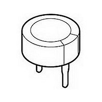
222219612474 Vishay, 222219612474 Datasheet - Page 5

222219612474
Manufacturer Part Number
222219612474
Description
Manufacturer
Vishay
Datasheet
1.222219612474.pdf
(7 pages)
Specifications of 222219612474
Tolerance (+ Or -)
-20% to 80%
Voltage
5.5VDC
Operating Temp Range
-25C to 70C
Mounting Style
Through Hole
Construction
Stacked Coin
Dcl
216uA
Lead Spacing (nom)
5mm
Product Length (mm)
Not Requiredmm
Product Depth (mm)
Not Requiredmm
Product Height (mm)
7.5mm
Product Diameter (mm)
21mm
Lifetime
1000
Capacitance
470000uF
Package / Case
Not Required
Lead Free Status / RoHS Status
Compliant
www.vishay.com
166
196 DLC
Vishay BCcomponents
DISCHARGE CHARACTERISTICS
Backup time of 196 DLC series capacitors depends on
minimum memory holding voltage and discharge current
(corresponding with the current consumption of the load).
For minimum backup times of standard and vertical
miniaturized
≥ 24 hours).
backup
backup
time
time
(s)
(s)
10
10
10
10
10
10
10
10
10
10
4
6
5
4
3
Fig.10 Typical backup time as a function of discharge current
10
5
4
3
2
10
Fig.9 Typical backup time as a function of discharge current
Curve 1: 1.0 F, 5.5 V
Curve 2: 0.47 F, 5.5 V
Curve 3: 0.22 F, 5.5 V
Curve 4: 0.1 F, 5.5 V
Curve 5: 0.047 F, 5.5 V
Voltage drop:
from 5.0 to 2.0 V
-3
-3
Curve 1: 1.0 F, 5.5 V
Curve 2: 0.47 F, 5.5 V
Curve 3: 0.22 F, 5.5 V
Curve 4: 0.1 F, 5.5 V
Curve 5: 0.047 F, 5.5 V
Voltage drop from 5.0 to 3.5 V
series
10
10
-2
-2
see Figs 9 and 10
10
10
-1
-1
For technical questions contact: aluminumcaps1@vishay.com
discharge current (mA)
discharge current (mA)
(charging
1
1
Double Layer Capacitors
1
2
3
4
5
1
2
3
4
5
MGA696
MGA695
time
10
10
Figure 11 shows the backup time when a 196 DLC capacitor
is discharged by a constant resistance
(charging time ≥ 24 hours).
The horizontal axis shows the initial value of discharge
current if 5 V is connected to the capacitor via a fixed series
resistor.
EXAMPLE: 1 µA CORRESPONDS TO 5 MΩ AND 0.1 µA
CORRESPONDS TO 50 MΩ
The vertical axis shows that period of time during which the
voltage drops from 5 to 2 V.
backup
time
(s)
10
10
10
1
2
3
10
-2
Curve 1: 1.0 F, 5.5 V
Curve 2: 0.47 F, 5.5 V
Curve 3: 0.22 F, 5.5 V
Curve 4: 0.1 F, 5.5 V
Curve 5: 0.047 F, 5.5 V
Voltage drop from 5.0 to 2.0 V
by means of a fixed resistor
Fig.11 Typical backup time as a function
10
-1
of initial discharge current
1
initial value discharge current (mA)
Document Number: 28362
10
5
4
1
2
3
Revision: 15-Apr-08
10
2
MLB203
10
3


