MAL219632104E3 Vishay, MAL219632104E3 Datasheet - Page 4
MAL219632104E3
Manufacturer Part Number
MAL219632104E3
Description
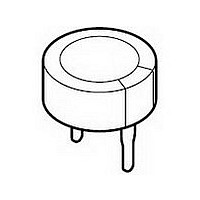
CAPACITOR, DOUBLE LAYER, 0.1F, 5.5V
Manufacturer
Vishay
Datasheet
1.MAL219612104E3.pdf
(7 pages)
Specifications of MAL219632104E3
Capacitance
100000uF
Tolerance (+ Or -)
-20% to 80%
Voltage
5.5VDC
Operating Temp Range
-25C to 70C
Mounting Style
Through Hole
Construction
Stacked Coin
Dcl
100uA
Lead Spacing (nom)
5mm
Product Length (mm)
Not Requiredmm
Product Depth (mm)
4.5mm
Product Height (mm)
13mm
Product Diameter (mm)
11.5mm
Lifetime
1000
Package / Case
Not Required
Capacitance Tolerance
-20% To +80%
Voltage Rating
5.5V
Capacitor Case Style
Radial
No. Of Pins
2
Capacitor Mounting
Through Hole
Lead Spacing
5mm
Operating Temperature
RoHS Compliant
Operating Temperature Range
-25°C To
Rohs Compliant
Yes
Capacitor Terminals
Radial Leaded
Lead Free Status / RoHS Status
Compliant
Available stocks
Company
Part Number
Manufacturer
Quantity
Price
Company:

Part Number:
MAL219632104E3
Manufacturer:
VISHAY
Quantity:
12 000


MEASURING OF CHARACTERISTICS
CAPACITANCE (C)
Capacitance shall be measured by constant current discharge method.
Capacitance value C
T and rated voltage U
INTERNAL RESISTANCE (R
Document Number: 28362
Revision: 15-Apr-08
C F ( )
R
DISCHARGE CURRENT AS A FUNCTION OF RATED CAPACITANCE
Rated capacitance, C
Discharge current, I
I
( )
Ω
1 kHz
=
=
Fig.4 Voltage diagram for capacitance measurement
Fig.5 Test circuit for capacitance measurement
Fig.6 Test circuit for R
I
------------------------------------------------------- -
D
V
--------------- -
(V)
U
2.0
10
U
(
C
R
mA
0
( )
–
V
3
U
+
)
R
×
( ) 2
V
10
PARAMETER
–
–
D
3
A
30 min
R
R
×
R
V
T s ( )
is given by discharge current I
, according to the following equation:
1 mA
+
I
measurement
C
C
A
T (s)
For technical questions contact: aluminumcaps1@vishay.com
I
) AT 1 kHz
Constant
current
discharger
Double Layer Capacitors
V
time
0.047
D
, time
0.1
0.1
LEAKAGE CURRENT (I
Leakage current shall be measured after 30 minutes
application of rated voltage U
I
(µA)
L
(
10
I
10
1
L
μA
0.22
2
1
)
Fig.7 Test circuit for leakage current
=
VALUE
Fig.8 Typical leakage current as a function of time
V V
------------ -
10
( )
0.33
–
4
+
10
0.47
Vishay BCcomponents
20
R
S
0.68
R
1.0
100 Ω
V
:
L
)
30
1.0
Curve 1: 1.0 F, 5.5 V
Curve 2: 0.47 F, 5.5 V
Curve 3: 0.22 F, 5.5 V
Curve 4: 0.1 F, 5.5 V
Curve 5: 0.047 F, 5.5 V
R
S
= 100 Ω
196 DLC
www.vishay.com
40
+
time (hours)
UNIT
mA
F
C
1
2
3
4
5
165
50
Related parts for MAL219632104E3
Image
Part Number
Description
Manufacturer
Datasheet
Request
R

Part Number:
Description:
357-036-542-201 CARDEDGE 36POS DL .156 BLK LOPRO
Manufacturer:
Vishay
Datasheet:
Part Number:
Description:
357-036-542-201 CARDEDGE 36POS DL .156 BLK LOPRO
Manufacturer:
Vishay
Datasheet:
Part Number:
Description:
357-036-542-201 CARDEDGE 36POS DL .156 BLK LOPRO
Manufacturer:
Vishay
Datasheet:
Part Number:
Description:
357-036-542-201 CARDEDGE 36POS DL .156 BLK LOPRO
Manufacturer:
Vishay
Datasheet:
Part Number:
Description:
357-036-542-201 CARDEDGE 36POS DL .156 BLK LOPRO
Manufacturer:
Vishay
Datasheet:
Part Number:
Description:
357-036-542-201 CARDEDGE 36POS DL .156 BLK LOPRO
Manufacturer:
Vishay
Datasheet:
Part Number:
Description:
357-036-542-201 CARDEDGE 36POS DL .156 BLK LOPRO
Manufacturer:
Vishay
Datasheet:
Part Number:
Description:
357-036-542-201 CARDEDGE 36POS DL .156 BLK LOPRO
Manufacturer:
Vishay
Datasheet:
Part Number:
Description:
357-036-542-201 CARDEDGE 36POS DL .156 BLK LOPRO
Manufacturer:
Vishay
Datasheet:
Part Number:
Description:
357-036-542-201 CARDEDGE 36POS DL .156 BLK LOPRO
Manufacturer:
Vishay
Datasheet:
Part Number:
Description:
357-036-542-201 CARDEDGE 36POS DL .156 BLK LOPRO
Manufacturer:
Vishay
Datasheet:
Part Number:
Description:
357-036-542-201 CARDEDGE 36POS DL .156 BLK LOPRO
Manufacturer:
Vishay
Datasheet:
Part Number:
Description:
357-036-542-201 CARDEDGE 36POS DL .156 BLK LOPRO
Manufacturer:
Vishay
Datasheet:
Part Number:
Description:
357-036-542-201 CARDEDGE 36POS DL .156 BLK LOPRO
Manufacturer:
Vishay
Datasheet:
Part Number:
Description:
357-036-542-201 CARDEDGE 36POS DL .156 BLK LOPRO
Manufacturer:
Vishay
Datasheet: