HL02506E10K00JE Vishay, HL02506E10K00JE Datasheet - Page 3
HL02506E10K00JE
Manufacturer Part Number
HL02506E10K00JE
Description
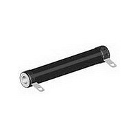
RESISTOR WIREWOUND, 10KOHM, 25W, 5%
Manufacturer
Vishay
Type
Wirewoundr
Series
HLr
Specifications of HL02506E10K00JE
Resistance
10kohm
Temperature Coefficient
±30
Power Rating(s)
25W
Tolerance (+ Or -)
5%
Mounting Style
Bolt-On
Construction
Tubular
Operating Temp Range
-55C to 350C
Case Style
Ceramic Hi Temp Sil
Termination Style
Radial Lug
Military Standard
Not Required
Failure Rate
Not Required
Product Length (mm)
50.8mm
Product Height (mm)
Not Requiredmm
Product Depth (mm)
Not Requiredmm
Resistance Tolerance
± 5%
Power Rating
25W
Resistor Element Material
Wirewound
Resistor Case Style
Radial Lugs
No. Of Pins
2
Lead Free Status / RoHS Status
Compliant


MOUNTING HARDWARE
Mounting hardware is available for HL resistors, see HL Brackets and Sliders datasheet for more information:
www.vishay.com/doc?30279
MATERIAL SPECIFICATIONS
Element: Copper-nickel alloy of nickel-chrome alloy,
depending on resistance value
Core: Ceramic, steatite
Coating: Special high temperature silicone
Standard Terminals: Model “E” terminals are tinned steel
Terminal Bands: Steel
Part Marking: Vishay Dale, model, wattage, value,
tolerance, date code
DERATING
Document Number: 30208
Revision: 23-Feb-11
TECHNICAL SPECIFICATIONS
PARAMETER
Temperature Coefficient
Short Time Overload
Dielectric Withstanding Voltage
Maximum Working Voltage
Insulation Resistance
Operating Temperature Range
PERFORMANCE
TEST
Thermal Shock
Short Time Overload
Dielectric Withstanding Voltage
Low Temperature Storage
High Temperature Exposure
Humidity
Load Life
Moisture Resistance
Shock, Specified Pulse
Vibration, High Frequency
Wirewound Resistors, Industrial Power, Tubular (HL),
Rated power applied until thermally stable, then a minimum of
10 x rated power for 5 s
1000 V
- 55 °C for 24 h
250 h at + 350 °C
75 °C, 90 % to 100 % RH, 240 h
1000 h at rated power, + 25 °C, 1.5 h “ON”, 0.5 h “OFF”
MIL-STD-202 Method 106, 7b not applicable
MIL-STD-202 Method 213, 100 g’s for 6 ms, 10 shocks
Frequency varied 10 Hz to 2000 Hz, 20 g peak, 2 directions 6 h each
15 min at - 55 °C
ppm/°C
120
100
For technical questions, contact:
UNIT
80
60
40
20
- 65 - 50
V
°C
0
RMS
V
-
AC
Non-Inductive Tubular (NHL)
for 1 min
0
25
50
CONDITIONS OF TEST
± 30 for 10 and above; ± 50 for 1 to 9.9 ; ± 90 for 0.1 to 0.99
1000 M minimum dry, 100 M minimum after moisture test
ww2bresistors@vishay.com
150
AMBIENT TEMPERATURE IN °C
NHL NON-INDUCTIVE
Models of equivalent physical and electrical specifications
are available with non-inductive (Aryton-Perry) winding.
They are identified by adding the letter N to the front of the
HL type designation (NHL225 for example). For NHL models
maximum resistance values are lower, see Standard
Electrical Specifications table.
HL, NHL RESISTOR CHARACTERISTICS
1000, from terminal to mounting hardware
10 x rated power for 5 s
250
- 55 to + 350
(P x R)
1/2
350
± (2.0 % + 0.05 ) R
± (2.0 % + 0.05 ) R
± (0.1 % + 0.05 ) R
± (2.0 % + 0.05 ) R
± (2.0 % + 0.05 ) R
± (5.0 % + 0.05 ) R
± (3.0 % + 0.05 ) R
± (2.0 % + 0.05 ) R
± (0.2 % + 0.05 ) R
± (0.2 % + 0.05 ) R
TEST LIMITS
Vishay Dale
HL, NHL
www.vishay.com
3
Related parts for HL02506E10K00JE
Image
Part Number
Description
Manufacturer
Datasheet
Request
R

Part Number:
Description:
357-036-542-201 CARDEDGE 36POS DL .156 BLK LOPRO
Manufacturer:
Vishay
Datasheet:
Part Number:
Description:
357-036-542-201 CARDEDGE 36POS DL .156 BLK LOPRO
Manufacturer:
Vishay
Datasheet:
Part Number:
Description:
357-036-542-201 CARDEDGE 36POS DL .156 BLK LOPRO
Manufacturer:
Vishay
Datasheet:
Part Number:
Description:
357-036-542-201 CARDEDGE 36POS DL .156 BLK LOPRO
Manufacturer:
Vishay
Datasheet:
Part Number:
Description:
357-036-542-201 CARDEDGE 36POS DL .156 BLK LOPRO
Manufacturer:
Vishay
Datasheet:
Part Number:
Description:
357-036-542-201 CARDEDGE 36POS DL .156 BLK LOPRO
Manufacturer:
Vishay
Datasheet:
Part Number:
Description:
357-036-542-201 CARDEDGE 36POS DL .156 BLK LOPRO
Manufacturer:
Vishay
Datasheet:
Part Number:
Description:
357-036-542-201 CARDEDGE 36POS DL .156 BLK LOPRO
Manufacturer:
Vishay
Datasheet:
Part Number:
Description:
357-036-542-201 CARDEDGE 36POS DL .156 BLK LOPRO
Manufacturer:
Vishay
Datasheet:
Part Number:
Description:
357-036-542-201 CARDEDGE 36POS DL .156 BLK LOPRO
Manufacturer:
Vishay
Datasheet:
Part Number:
Description:
357-036-542-201 CARDEDGE 36POS DL .156 BLK LOPRO
Manufacturer:
Vishay
Datasheet:
Part Number:
Description:
357-036-542-201 CARDEDGE 36POS DL .156 BLK LOPRO
Manufacturer:
Vishay
Datasheet:
Part Number:
Description:
357-036-542-201 CARDEDGE 36POS DL .156 BLK LOPRO
Manufacturer:
Vishay
Datasheet:
Part Number:
Description:
357-036-542-201 CARDEDGE 36POS DL .156 BLK LOPRO
Manufacturer:
Vishay
Datasheet:
Part Number:
Description:
357-036-542-201 CARDEDGE 36POS DL .156 BLK LOPRO
Manufacturer:
Vishay
Datasheet: