788157-2 TE Connectivity, 788157-2 Datasheet - Page 8
788157-2
Manufacturer Part Number
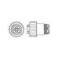
788157-2
Description
CIR CONN PLUG SIZE 13, 9POS FREE HANGING
Manufacturer
TE Connectivity
Type
CPCr
Series
CPC Series 1r
Specifications of 788157-2
Contact Gender
SKT
Gender
PL
Number Of Contacts
9POS
Shell Size / Insert Arrangement
13-9
Mounting Style
Cable
Termination Method
Crimp
Body Orientation
Straight
Strain Relief
No
Contact Classification
9Signal
Product Diameter (mm)
27.94mm
Product Length (mm)
36.2mm
Connector Type
Circular Industrial
Connector Body Material
Nylon
Connector Mounting
Free Hanging
Connector Shell Size
13
Rohs Compliant
Yes
Mounting
Cable Mount
Agency Approvals
UL/CSA/VDE/SAE/ASAE
Angle
Straight
Application
Commercial
Brand/series
Series 1
Color
Black
Diameter, Insulation
0.065 to 0.1 "
Flammability Rating
UL94-V0
Housing Type
Plastic
Insert Arrangement
13-9
Material, Housing
Nylon
Mating Type
Threaded
Mounting Type
Free Hanging
Primary Type
Circular Plastic Connector
Shell Size
13
Voltage, Rating
600 VAC/VDC
Mount
Free Hanging
Mount Angle
Straight
Shell Type
All Plastic
Product Series
Series 1
Thread Size
3/4 - 20 UNEF-2A
Sealed
Yes
Mating Retention Type
Threaded Coupling
Vde Tested
No
Seal Type
Wire Entry
Number Of Positions
9
Number Of Signal Positions
9
Contact Type
Socket
Reverse Gender
Standard
Connector Style
Plug
Mating Alignment Type
Keyed
Housing Material
Nylon
Housing Color
Black
Environmental Protection
With
Reverse Numbering
Without
Rohs/elv Compliance
RoHS compliant, ELV compliant
Lead Free Solder Processes
Not relevant for lead free process
Rohs/elv Compliance History
Always was RoHS compliant
Fluid Resistance
Immersion
Accepts Wire Insulation Diameter, Range (mm [in])
1.65 – 3.05 [0.065 – 0.120]
Lead Free Status / RoHS Status
Compliant
Available stocks
Company
Part Number
Manufacturer
Quantity
Price
Company:

Part Number:
788157-2
Manufacturer:
TE
Quantity:
20 000


8
The total current capacity of
each contact in a given
connector is dependent upon
the heat rise resulting from the
combination of electrical loads
of the contacts in the connector
arrangement and the maximum
ambient temperature in which
the connector will be operating.
Caution must be taken so that
this combination of conditions
does not cause the internal
temperature of the connector to
exceed the maximum operating
temperature of the housing
material. Several variables
which must be considered
when determining this
maximum current capability for
your application are:
I
Current Rating Verification
Can a contact rated at 10 amps
carry 10 amps?
Maybe yes, but probably not.
The reason lies in the test
conditions used to rate the
contact. If these conditions do
not adequately reflect the appli-
cation conditions, the actual
allowable current levels may be
lower than specified levels. For
example, many manufacturers,
including Tyco Electronics, test
a single contact in air. This
gives an accurate measure of
the basic current-carrying
capacity of the contact. Use the
contact alone in air and it can
certainly carry 10 ampere. Use
it in a multi-position connector
surrounded by other current-
carrying contacts or in high
ambient temperatures, and the
contact should carry less
current.
Similarly, as the contact ages
and stress relaxation, environ-
mental cycling, and other
degradation factors take their
toll, the contact’s current-
carrying capacity decreases.
A prudent design must set
current levels for such end-of-
Catalog 82021
Revised 7-07
www.tycoelectronics.com
Wire Size—Larger wire will
carry more current since it
has less internal resistance
to current flow and generates
less heat. The wire also
conducts heat away from the
connector.
Dimensions are in inches and
millimeters unless otherwise
specified. Values in brackets
are metric equivalents.
AMP Circular Connectors for
Commercial Signal and Power Applications
Current Carrying Capabilities
I
design-life (EODL) conditions.
Practical current-carrying capac-
ity is not an absolute, but an
application-dependent condition.
New Method Simplifies Ratings
To help the designer set the
appropriate current level, Tyco
Electronics has developed a
method of specifying current-
carrying capacity. This method
takes into account the various
application factors that influ-
ence current rating.
The method can be summarized
as follows:
I
I
I
I
75
60
45
30
15
0
Connector Size—In general,
with more circuits in a
connector, less current per
contact can be carried.
The contact is aged to EODL
conditions by durability
cycling, thermal cycling, and
environmental exposure.
The contact’s resistance
stability is verified.
The current necessary to
produce the specified tempera-
ture rise is measured. This
T-rise is usually 30°C.
A rating factor is determined
to allow derating of multiple
contacts in the same housing
and for different conductor
sizes.
60
CONTACT CURRENT GUIDE Maximum Current (Amperes) for Largest Wire Size
56
Dimensions are shown for
reference purposes only.
Specifications subject
to change.
50
45
I
Temperature
One other factor influencing
current levels is the maximum
operating temperature, for
example, 105°C. If the appli-
cation has a high ambient
temperature (over 75°C) the
contact’s T-rise is limited by
the maximum operating
temperature. For example, an
application temperature of
90°C limits the contact T-rise
to 15°C. Since current
produces heat (the I
current must be lowered to
limit the T-rise.
A contact’s T-rise depends not
only on its I
also on its ability to dissipate
the heat. Consider a contact in
a multi-contact housing. Joule
heating in multiple contacts will
raise the local ambient temper-
ature. Since the contact will not
be able to dissipate its own
heat as well by convection, the
maximum T-rise will be realized
at a lower current level. Conse-
quently, the allowable current
level must be lower to maintain
an acceptable T-rise.
For a given connector, the
current level will be set by the
35
Current Load Distribution—
Spreading those lines with
greater current loads through-
out the connector, particularly
around the outer perimeter,
will enhance heat dissipation.
23
USA: 1-800-522-6752
Canada: 1-905-470-4425
Mexico: 52-55-1106-0800
C. America: 57-1-254-4444
2
R Joule heating, but
13
Note:
are RoHS Compliant.
11.85
2
R law), the
All part numbers
7.5
I
loading density. A connector
containing 50% current-carrying
contacts will permit higher
currents (per contact) than a
connector will at 75% loading.
The loading percentage assumes
an even distribution of contacts
within the housing. If all 10
contacts are grouped together in
one section of a 20-position
connector, the loading density
may approach 100%.
The Importance of EODL
As stated, T-rise in a contact
depends on both resistance and
current. As it ages, a contact’s
resistance will increase. The
contact designer will specify a
maximum resistance for the
contact, this level is the end-of-
design-life resistance. Before
the contact is tested for current,
Tyco Electronics subjects it to a
sequence of tests that exercises
the major failure mechanisms
and thereby simulates EODL
conditions. Conditioning
includes mating cycling, indus-
trial mixed-flowing gases,
humidity and temperature
cycling, and vibration to
sequentially introduce wear,
corrosion, stress relaxation,
and mechanical disturbance.
Ambient Temperature—With
higher ambient temperatures,
less current can be carried.
South America: 55-11-2103-6000
Hong Kong: 852-2735-1628
Japan: 81-44-844-8013
UK: 44-208-420-8341
Type XII Upgrade
Size 8 Upgrade
.125 POWERBAND Contact
Size 8
Type XII
Type I, Type II/III +
Upgrade
Type III + , Type II,
Type III + Posted
Size 20 Upgrade
20 DF
Related parts for 788157-2
Image
Part Number
Description
Manufacturer
Datasheet
Request
R

Part Number:
Description:
SLD CPC 13-9 PLUG,STD,SM INS
Manufacturer:
TE Connectivity
Datasheet:

Part Number:
Description:
Printers THERMAL PRINTER HS-SLEEVE MARKER
Manufacturer:
TE Connectivity


Part Number:
Description:
High Speed / Modular Connectors 30P HEADER ASSY
Manufacturer:
TE Connectivity
Datasheet:

Part Number:
Description:
High Speed / Modular Connectors REC 6X005P R/A LT B-PLANE HS3
Manufacturer:
TE Connectivity
Datasheet:

Part Number:
Description:
High Speed / Modular Connectors 2MM HM RCPT 50P R/A AU
Manufacturer:
TE Connectivity
Datasheet:

Part Number:
Description:
High Speed / Modular Connectors 2MM HM RCPT 50P R/A AU
Manufacturer:
TE Connectivity
Datasheet:


Part Number:
Description:
Manufacturer:
TE Connectivity
Datasheet:


Part Number:
Description:
Manufacturer:
TE Connectivity
Datasheet:

Part Number:
Description:
Manufacturer:
TE Connectivity
Datasheet:

Part Number:
Description:
Manufacturer:
TE Connectivity
Datasheet: