66570-3 TE Connectivity, 66570-3 Datasheet - Page 4
66570-3
Manufacturer Part Number
66570-3
Description
D SUB CONTACT, PIN, 18AWG, SOLDER
Manufacturer
TE Connectivity
Type
Contactr
Series
AMPLIMITE HDP-20r
Specifications of 66570-3
Number Of Contacts
1POS
Number Of Terminals
1
Plug / Receptacle
PIN
Contact Plating
Au over Pd Ni
Contact Pitch (mm)
Not Requiredmm
Body Orientation
Straight
Mounting Style
Cable
Number Of Ports
1Port
Number Of Contact Rows
Not Required
Operating Temp Range
-55C to 105C
Termination Method
Solder Cup
Current Rating
3.7A
Housing Material
Not Required
Contact Material
Brass
Operating Voltage (max)
250VAC
Product Length (mm)
14.86mm
Product Depth (mm)
2.15mm
Wire Size (awg)
18
Contact Termination
Solder
Contact Type
Signal
Accessory Type
Pin & Socket Contact
Gender
Pin
Rohs Compliant
Yes
Contact Gender
Pin
Product Type
Contact
Product Series
HDP-20 (Crimp Snap)
Termination Method To Wire/cable
Solder
Insulation Support
No
Grade
Standard
Contact Retention In Housing
Crimp Snap-In
Solder Tail Contact Plating
Gold Flash over Nickel
Pin Diameter (mm [in])
1.02 [0.040]
Wire Range (mm² [awg])
0.8 - 0.9 [18]
Used With
CPC Connectors, AMPLIMITE HDP-20
Contact Base Material
Brass
Contact Plating, Mating Area, Material
Gold Flash over Palladium Nickel or Gold (30) over Nickel
Contact Size
20
Contact Configuration
Solder Cup
Rohs/elv Compliance
RoHS compliant, ELV compliant
Lead Free Solder Processes
Not relevant for lead free process
Rohs/elv Compliance History
Always was RoHS compliant
Packaging Method
Loose Piece
Lead Free Status / RoHS Status
Compliant


4
4
Practical Values
The current-rating method
gives designers practical val-
ues applicable to their applica-
tions. While the specified
current levels for a contact may
be lower than for other testing
methods, they are more realis-
tic and simplify the system
design process.
“Spec-manship” is replaced by
a realistic assessment of the
current-carrying capacity of a
contact under varying condi-
tions of temperature, connector
loading, and wire size.
Connector/Contact
Acceptability
As previously stated, choosing
the correct connector/contact
combination is fundamental to
the successful function of all
connectors. The Selection
Chart shown below, is
designed to simplify your
choice of connectors and their
acceptable contacts. Once you
have selected the wire size,
current-carrying capacity need,
number of positions required,
and the type of contacts need-
ed in your choice of connector,
refer to this matrix for a quick
look at exactly what is accept-
able in a given connector type.
Contact Selection Chart
Next are rating factors, a table
of multipliers to account for
connector loading and for
smaller wire sizes. The
designer first determines the
base current for the ambient
conditions of the application;
then multiplies this base cur-
rent by the rating factors to
find the current level for the
application’s loading factor
and wire size.
(.125 POWERBAND)
CPCSeries 1
CPC Series 2
CPC Series 3
CPC Series 4
CPCSeries 5
CPCSeries 6
Connector
“G” Series
Metrimate
Metrimate
Metrimate
M Series
M Series
Drawer
Drawer
Special
Type
& Size 20
Upgrade
20 DF
Dimensions are in inches and
millimeters unless otherwise
specified. Values in brackets
are metric equivalents.
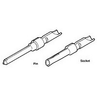
Precision Pin and Socket Contacts
Precision Pin and Socket Contacts
Current Carrying Capabilities
Technical Documents
Technical Documents consist
of Product Specifications and
Application Specifications.
Product Specifications define
the performance characteristics
of the product; i.e., Current
Rating, Temperature Rating,
etc. They are intended for the
Design or Component
Engineer. Application
Specifications describe how
the product is to be applied;
i.e., Crimping, Assembling,
etc. They are intended for
Manufacturing and Operation/
Set Up Personnel. Where Appli-
cation Specifications are not
available, an Instruction Sheet
is provided. Additional
Instruction Sheets on the prod-
uct may be available. Please
contact Technical Support:
1-800-522-6752.
Type I
An Example:
To demonstrate the method of
specifying current, consider the
following application conditions;
an ambient temperature of
65°C, a 50% loading of con-
tacts in the housing, and
20 AWG [0.6mm
From Figure 1, the base cur-
rent rating is 14 ampere with
18 AWG [0.8mm
Figure 2, the rating factor for
50% loading and 20 AWG
[0.6mm
The specific rating for this
application is the product of
the base rating and the rating
factor:
Each of the contacts can
carry 9.5 ampere.
However, if the ambient tem-
perature is 80°C the allow-
able T-rise becomes 25°C.
The base current must be
lowered to 12.8 ampere so
that the 105°C maximum
operating temperature is not
exceeded. The current rating
then becomes:
12.8 x 0.68 = 8.7 ampere.
14 x 0.68 = 9.5 ampere
2
] wire is 0.68.
Type II
2
] wire.
2
Dimensions are shown for
reference purposes only.
Specifications subject to change.
] wire.
Type III + &
Type II/III +
Upgrade
Rating factors allow the base current to be adjusted for various connec-
tor loading and wire sizes.
Type III +
Technical Document Selection Chart
Posted
.125 POWERBAND
M Series Posted
Size 8 Upgrade
(Continued)
Mini Coax
Type III+
Sub-Mini
Contact
Type XII
Type VI
Type II
Type I
Size 8
20 DF
Type
Coax
& Type XII
Upgrade
Type XII
Technical Support
USA: 1-800-522-6752
Canada: 1-905-475-6222
Mexico: 01-800-733-8926
Specifications
POWERBAND
108-40005
108-10108
108-10039
108-10042
108-10038
108-10037
108-10042
108-01317
108-14497
108-12021
108-12008
108-12011
Product
.125
—
Figure 2
Upgrade
&Size 8
Central America: 52-55-5-729-0425
South America: 55-11-3611-1514
www.tycoelectronics.com
Specifications
Size 8
Application
114-10000
114-40030
114-10037
114-10026
114-10004
114-10007
114-10005
114-10043
114-10014
—
—
—
—
Mini-Coax
Catalog 65910
Instruction
408-2024-3
408-09155
Revised 1-03
408-1770
Sheet
Sub-Mini
—
—
—
—
—
—
—
—
—
Coax
Related parts for 66570-3
Image
Part Number
Description
Manufacturer
Datasheet
Request
R

Part Number:
Description:
D SUB CONTACT, PIN, 18AWG, SOLDER
Manufacturer:
TE Connectivity
Datasheet:

Part Number:
Description:
20 DF PIN PLTD
Manufacturer:
TE Connectivity
Datasheet:

Part Number:
Description:
SOCKET KIT, D, 9WAY
Manufacturer:
HARTING
Datasheet:
Part Number:
Description:
PLUG KIT, D, 9WAY
Manufacturer:
HARTING
Datasheet:
Part Number:
Description:
PLUG KIT, D, 25WAY
Manufacturer:
HARTING
Datasheet:

Part Number:
Description:
High Speed / Modular Connectors 30P HEADER ASSY
Manufacturer:
TE Connectivity
Datasheet:

Part Number:
Description:
High Speed / Modular Connectors REC 6X005P R/A LT B-PLANE HS3
Manufacturer:
TE Connectivity
Datasheet:

Part Number:
Description:
High Speed / Modular Connectors 2MM HM RCPT 50P R/A AU
Manufacturer:
TE Connectivity
Datasheet:

Part Number:
Description:
High Speed / Modular Connectors 2MM HM RCPT 50P R/A AU
Manufacturer:
TE Connectivity
Datasheet:


Part Number:
Description:
Manufacturer:
TE Connectivity
Datasheet:


Part Number:
Description:
Manufacturer:
TE Connectivity
Datasheet:

Part Number:
Description:
Manufacturer:
TE Connectivity
Datasheet:

Part Number:
Description:
Manufacturer:
TE Connectivity
Datasheet: