56F414-001 Spectrum Control, 56F414-001 Datasheet - Page 18
56F414-001
Manufacturer Part Number
56F414-001
Description
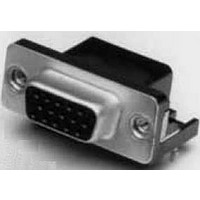
CONNECTOR, D SUB FLTR, RECEPTACLE, 15POS
Manufacturer
Spectrum Control
Type
Filtered D-Subr
Series
Fr
Specifications of 56F414-001
Number Of Contacts
15POS
Number Of Terminals
15
Plug / Receptacle
SKT
Contact Plating
Gold Over Nickel
Contact Pitch (mm)
2.74mm
Body Orientation
Right Angle
Mounting Style
Through Hole
Number Of Ports
1Port
Number Of Contact Rows
2
Operating Temp Range
-40C to 105C
Termination Method
Solder
Current Rating
5A
Housing Material
Steel
Contact Material
Phosphor Bronze
Product Length (mm)
39.14mm
Product Depth (mm)
19.2mm
Product Height (mm)
12.55mm
No. Of Contacts
15
D Sub Shell Size
DA
Connector Body Material
Metal
Gender
Receptacle
Contact Termination
Right Angle Through Hole
Connector Type
Filtered D Sub
Peak Reflow Compatible (260 C)
No
Rohs Compliant
Yes
Lead Free Status / RoHS Status
Compliant
Available stocks
Company
Part Number
Manufacturer
Quantity
Price
Company:

Part Number:
56F414-001
Manufacturer:
API Technologies Corp
Quantity:
457
Company:
Part Number:
56F414-001-HD
Manufacturer:
API Technologies Corp
Quantity:
457


145
Series 600 Hi-Density
Filtered Connectors
The miniaturization of electronic systems and sub-
systems is pushing designers to increase circuit
densities within smaller packages. To address this
growing need, Spectrum Control has developed a
line of filtered Hi-Density D-subminiature connectors.
This new line of connectors incorporates the high
performance and reliable filtering of Spectrum’s
standard D-subs in the Hi-Density format.
Features
s
s
s
s
s
Mechanical Specifications:
Same as Series 700 connectors, page 150.
Electrical Specifications: Hi-Density Connectors
Filter designation “G” for grounded contacts, “I” for insulated (not filtered) contacts.
Filter designation “O” for omitted contact and no hole in ground plane.
Ordering Information
Example:
D-Sub
Connector
Hi-Density
F - RoHS compliant version
SPECTRUM CONTROL INC. • 8031 Avonia Rd. • Fairview, PA 16415 • Phone: 814-474-2207 • Fax: 814-474-2208 • Web site: www.spectrumcontrol.com
SPECTRUM CONTROL GmbH • Hansastrasse 6 • 91126 Schwabach, Germany • Phone: (49)-9122-795-0 • Fax: (49)-9122-795-58
nations
Desig-
56 -
- Standard connector
Filter
Connectors designed to MIL-C-24308
Capacitance values from 85 pF to 4000 pF
Filter type feed-thru C
Selectively specify and filter each contact position
Available in feed-thru capacitive configurations
15
16
18
19
Circuits
Filter
C
56-605-015-LI
6 0 5 - 0 15
Shell
Size**
0 = 15
1 = 26
2 = 44
3 = 62
4 = 78
1000 pF
4000 pF
180 pF
Value
85 pF
Capacitance
Contact/Termination
1 - Pin to solder cup
2 - Pin to 90° PCB mount*
3 - Socket to PCB mount
4 - Socket to 90° PCB*
5 - Pin-socket adapter
7 - Pin to PCB mount
±25%
±25%
±25%
±25%
mount
Tol.
quency
Cut-off
(MHz)
3 dB
Max.
Fre-
5.1
1.3
60
28
Dielectric
-
standing
Voltage
With-
300V
300V
300V
300V
Special
0 = All
9 = Special
** Some shell sizes require minimum order quantity.
Note: VGA adapters also available. Consult factory
LI
Consult Spectrum Control for details.
positions
same
loading
Voltage DC
Working
-55°C to
+125°C
100V
100V
100V
100V
Insertion loss measured per MIL-STD-220, no load, 50 ohm source and load.
Electrical Specifications
Current Rating . . . . 3 Amps
RF Current Rating. . 0.3 Amps
Contact Resistance . . 15 milliohms maximum
UL Recognized. . . . . Under category of communication
This part number represents a Series 600 Hi-Density filtered D-Sub
connector with 15 contacts, pin-socket adapter configuration. The FT
filters have a capacitance value of 85 pF and the connector includes
4-40 locking inserts.
. . . . . . . . . . . . . . . .
MHz
—
—
—
5
8
Filter Designation
15 - 85 pF FT
16 - 180 pF FT
18 - 1,000 pF FT
19 - 4,000 pF FT
20 - Insulated contact
80
70
60
50
40
30
20
10
MHz
0
10
—
—
13
3
1MHz
Above curves represent application of proper
grounding fundamentals, for assistance consult
with Spectrum Control.
Typical Insertion Loss
Minimum Insertion Loss - Decibels (dB)
MHz
20
19
—
—
8
Capacitive Filter
10MHz
MHz
50
14
26
—
1
circuit accessories, File #E149046
MHz
100
20
31
1
8
* Required on right angle parts
Above data represents guaranteed minimum.
Frequency
MHz
100MHz
Options
50G = µ gold
GBL = Grounding board lock
200
10
25
37
6
LI = 4-40 inserts
S = Solder dip tails
18
16
19
15
MHz
500
16
18
32
45
GHz
1GHz 5GHz
21
25
35
48
1
GHz
22
26
41
52
2
GHz
20
24
39
47
5
Related parts for 56F414-001
Image
Part Number
Description
Manufacturer
Datasheet
Request
R

Part Number:
Description:
Power Line Filters Single Stage
Manufacturer:
Spectrum Control Inc.
Datasheet:
Part Number:
Description:
High Current Single Line Feed-thru Filters
Manufacturer:
Spectrum Control Inc.
Datasheet:
Part Number:
Description:
Switched And Fused Filtered Power Entry Modules
Manufacturer:
Spectrum Control Inc.
Datasheet:
Part Number:
Description:
Surface Mount Emi Filters
Manufacturer:
Spectrum Control Inc.
Datasheet:

Part Number:
Description:
(PSMx Series) Surface Mount EMI Filters
Manufacturer:
Spectrum Control
Datasheet: