56-402-001 Spectrum Control, 56-402-001 Datasheet - Page 21
56-402-001
Manufacturer Part Number
56-402-001
Description
D-Subminiature Connectors 9 PIN MALE
Manufacturer
Spectrum Control
Type
Filtered D-Subr
Series
400r
Datasheet
1.56-402-001.pdf
(104 pages)
Specifications of 56-402-001
Number Of Contacts
9POS
Number Of Terminals
9
Plug / Receptacle
PIN
Contact Plating
Gold Over Nickel
Contact Pitch (mm)
2.74mm
Body Orientation
Right Angle
Mounting Style
Through Hole
Number Of Ports
1Port
Number Of Contact Rows
2
Operating Temp Range
-40C to 105C
Termination Method
Solder
Current Rating
5A
Housing Material
Steel
Contact Material
Brass
Product Length (mm)
30.81mm
Product Depth (mm)
19.1mm
Product Height (mm)
12.55mm
Product
Filtered Hoods & Connectors
Number Of Positions / Contacts
9
Shell Plating
Tin
Gender
Male
Mounting Angle
Right
Termination Style
Solder Pin
Operating Temperature Range
- 40 C to + 105 C
Connector Type
D-Sub Ferrite Filtered
Number Of Rows
2
Lead Free Status / RoHS Status
Not Compliant
Lead Free Status / RoHS Status
Not Compliant, Lead free / RoHS Compliant
Available stocks
Company
Part Number
Manufacturer
Quantity
Price
Company:

Part Number:
56-402-001
Manufacturer:
API Technologies Corp
Quantity:
457


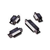
Hi-Density Filtered Adapter
for Telecommunications
Filter Performance
Insertion loss measured per MIL-STD-220, no load, 50 ohm source
and load. Above data represents guaranteed minimum.
Part Number for Ordering: #56-645-002
SPECTRUM CONTROL INC. • 8031 Avonia Rd. • Fairview, PA 16415 • Phone: 814-474-2207 • Fax: 814-474-2208 • Web site: www.spectrumcontrol.com
SPECTRUM CONTROL GmbH • Hansastrasse 6 • 91126 Schwabach, Germany • Phone: (49)-9122-795-0 • Fax: (49)-9122-795-58
(2.08)
.082
#4-40 UNC - 2B
Locking Inserts
4 plcs.
(11.18)
.440
(1.04)
.041
41
100 MHz . . . . . . . . . . . . . . . . . . . . . 20 dB
500 MHz . . . . . . . . . . . . . . . . . . . . . 32 dB
20 MHz . . . . . . . . . . . . . . . . . . . . . . 7 dB
50 MHz . . . . . . . . . . . . . . . . . . . . . 14 dB
1 GHz . . . . . . . . . . . . . . . . . . . . . 35 dB
2 GHz . . . . . . . . . . . . . . . . . . . . . 41 dB
5 GHz . . . . . . . . . . . . . . . . . . . . . 39 dB
Position numbers
shown for reference
(6.17)
.243
(4.83)
.190
Minimum Insertion Loss
.0475 (1.21)
21
(1.27)
.050
.095 (2.41)
60
2
2.635 (66.93)
2.062 (52.37)
Side View
Socket Face
2.406 (61.11)
Pin Face
(25.40)
(13.21)
1.000
(52.81)
.520
2.079
38
77
(6.05)
(4.83)
.238
.190
Dimensions in inches (mm)
19
58
(10.57)
.416
(15.62)
.615
100
50
50
40
30
20
10
0
0
0
1MHz
Above curves represent application of proper
grounding fundamentals, for assistance consult
with Spectrum Control.
* Reference Bellcore TR-NWT-1089, V pp = 1000V
Typical Insertion Loss
Pulse Wave Form* (10 x 1000)
t p
Peak Value – V pp
t r
1
Hall Value –
10MHz
2
t - - Time - - msec
Frequency
Vpp
100MHz
2
10 x 1000 Waveform
3
e t
4
Test Waveform
Parameters
t r = 10μsec
t p = 1000μs
1GHz
5
5GHz
6
148
Related parts for 56-402-001
Image
Part Number
Description
Manufacturer
Datasheet
Request
R


Part Number:
Description:
USB CONNECTOR, RECEPTACLE, 4POS, THD
Manufacturer:
Spectrum Control
Datasheet:
Part Number:
Description:
USB CONNECTOR, RECEPTACLE, 4POS, THD
Manufacturer:
Spectrum Control
Datasheet:
Part Number:
Description:
USB CONNECTOR, RECEPTACLE, 4POS, THD
Manufacturer:
Spectrum Control
Datasheet:

Part Number:
Description:
Rotary Switch,STRAIGHT,Number Of Positions:3,PC TAIL Terminal,ROTARY SHAFT,PCB Hole Count:12
Manufacturer:
Grayhill Inc
Datasheet:

Part Number:
Description:
Power Line Filters Single Stage
Manufacturer:
Spectrum Control Inc.
Datasheet:
Part Number:
Description:
High Current Single Line Feed-thru Filters
Manufacturer:
Spectrum Control Inc.
Datasheet:
Part Number:
Description:
Switched And Fused Filtered Power Entry Modules
Manufacturer:
Spectrum Control Inc.
Datasheet:
Part Number:
Description:
Surface Mount Emi Filters
Manufacturer:
Spectrum Control Inc.
Datasheet:

Part Number:
Description:
(PSMx Series) Surface Mount EMI Filters
Manufacturer:
Spectrum Control
Datasheet: