103185-7 TE Connectivity, 103185-7 Datasheet - Page 56
103185-7
Manufacturer Part Number
103185-7
Description
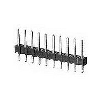
07 MODII HDR SRST B/A .100CL
Manufacturer
TE Connectivity
Type
Unshrouded Headerr
Datasheet
1.103185-7.pdf
(139 pages)
Specifications of 103185-7
Pitch (mm)
2.54mm
Gender
HDR
Number Of Contacts
7POS
Number Of Contact Rows
1
Mounting Style
Through Hole
Body Orientation
Straight
Contact Plating
Gold Over Nickel
Operating Temp Range
-65C to 105C
Termination Method
Solder
Current Rating (max)
3/ContactA
Contact Material
Phosphor Bronze
Housing Material
Thermoplastic
Housing Color
Black
Product Height (mm)
8.13mm
Product Length (mm)
17.37mm
Product Depth (mm)
2.34mm
Rohs Compliant
NO
Product Type
Connector
Mount Angle
Vertical
Pcb Mount Retention
Without
Surface Mount Compatible
No
Board Standoff
Without
Mounting Ears
Without
Mating Connector Lock
Without
Post Size (mm [in])
0.64 [.025]
Mating Post Length (mm [in])
5.84 [0.230]
Panel Mount Retention
Without
Current Rating (a)
3
Insulation Resistance (m?)
5,000
Dielectric Withstanding Voltage (v)
750
Termination Post Length (mm [in])
3.05 [0.120]
Solder Tail Contact Plating
Tin-Lead over Nickel
Header Type
Breakaway
Number Of Positions
7
Centerline (mm [in])
2.54 [0.100]
Row-to-row Spacing (mm [in])
2.54 [0.100]
Number Of Rows
1
Selectively Loaded
No
Mount Type
Printed Circuit Board
Contact Plating, Mating Area, Material
Gold (15)
Contact Shape
Square
Contact Base Material
Phosphor Bronze
Ul Flammability Rating
UL 94V-0
Rohs/elv Compliance
ELV compliant, 5 of 6 Compliant
Lead Free Solder Processes
Wave solder capable to 240°C
Approved Standards
UL E28476, CSA LR7189
Operating Temperature (°c)
-65 – +105
High Temperature Housing
No
High Speed Serial Data Connector
No
Lead Free Status / RoHS Status
Not Compliant


.025 [0.64] Square
Right-Angle Post
(with Detent Windows)
Material and Finish:
Housing—Black thermoplastic,
94V-0 rated
Posts—Copper alloy, plated as follows:
Plating A—Duplex plated .000030
[0.00076] gold on contact area,
.000100-.000200 [0.00254-0.00508]
tin-lead on solder area, with entire post
underplated .000050 [0.00127] nickel
Plating B—Duplex plated .000015
[0.00038] gold on contact area,
.000100-.000200 [0.00254-0.00508]
tin-lead on solder area, with entire post
underplated .000050 [0.00127] nickel
Plating C—.000100-.000200
[0.00254-0.00508] tin-lead over
.000050 [0.00127] nickel on entire post
Related Product Data:
Mateable Connectors:
AMPMODU Board Mount
Receptacles—pages 193, 196, 197
AMPMODU Wire-Applied
Receptacles—pages 233-236
AMPMODU MTE Receptacles—
pages 245, 246, 251
AMPMODU MT Receptacles—
pages 275, 276
Technical Documents
See mating connector for applicable
product and application specifications.
Catalog 1307819
Revised 6-04
www.tycoelectronics.com
(page 294):
Dimensions are in inches and
millimeters unless otherwise
specified. Values in brackets
are metric equivalents.
AMPMODU Interconnection System
Standard Profile Headers—Shrouded, with .066 [1.68] End Dimension,
Double-Row, .100 x .100 [2.54 x 2.54] Centerline
(Standoffs)
[16.23]
.639
[0.33]
.013
No. of
P o s .
1 0
1 2
1 4
1 6
1 8
2 0
2 2
2 4
2 6
2 8
3 0
6
8
(2 Plc.)
[1.68]
.066
[10.16]
[12.42]
.400
.489
1 . 0 1 2 [ 2 5 . 7 0 ]
1 . 1 1 2 [ 2 8 . 2 4 ] 1 . 0 3 2 [ 2 6 . 2 1 ]
1 . 2 1 2 [ 3 0 . 7 8 ] 1 . 1 3 2 [ 2 8 . 7 5 ] 1 . 0 0 0 [ 2 5 . 4 0 ] . 1 0 6 [ 2 . 6 9 ]
1 . 3 1 2 [ 3 3 . 3 2 ] 1 . 2 3 2 [ 3 1 . 2 9 ] 1 . 1 0 0 [ 2 7 . 9 4 ] . 1 0 6 [ 2 . 6 9 ] 1 . 0 0 6 [ 2 5 . 5 5 ]
1 . 4 1 2 [ 3 5 . 8 6 ] 1 . 3 3 2 [ 3 3 . 8 3 ] 1 . 2 0 0 [ 3 0 . 4 8 ] . 1 0 6 [ 2 . 6 9 ] 1 . 1 0 6 [ 2 8 . 0 9 ]
1 . 5 1 2 [ 3 8 . 4 0 ] 1 . 4 3 2 [ 3 6 . 3 7 ] 1 . 3 0 0 [ 3 3 . 0 2 ] . 1 0 6 [ 2 . 6 9 ] 1 . 2 0 6 [ 3 0 . 6 3 ]
1 . 6 1 2 [ 4 0 . 9 4 ] 1 . 5 3 2 [ 3 8 . 9 1 ] 1 . 4 0 0 [ 3 5 . 5 6 ] . 1 0 6 [ 2 . 6 9 ] 1 . 3 0 6 [ 3 3 . 1 7 ]
. 4 1 2 [ 1 0 . 4 6 ]
. 5 1 2 [ 1 3 . 0 0 ]
. 6 1 2 [ 1 5 . 5 4 ]
. 7 1 2 [ 1 8 . 0 8 ]
. 8 1 2 [ 2 0 . 6 2 ]
. 9 1 2 [ 2 3 . 1 6 ]
*±.003 [±0.08] tolerances not to accumulate
Recommended PC Board Hole Layout
A
(for .055 [1.40] min. thick PC board)
Dimensions are shown for
reference purposes only.
Specifications subject
to change.
within one connector pattern.
D
[0.89±0.08]
.035± . 0 0 3
.100*
. 3 3 2 [ 8 . 4 3 ]
. 4 3 2 [ 1 0 . 9 7 ]
. 5 3 2 [ 1 3 . 5 1 ]
. 6 3 2 [ 1 6 . 0 5 ]
. 7 3 2 [ 1 8 . 5 9 ]
. 8 3 2 [ 2 1 . 1 3 ]
. 9 3 2 [ 2 3 . 6 7 ]
[2.54]
[2.54]
.100
E
B
Typ.
Typ.
C
A
B
C
Dia. Typ.
D i m e n s i o n s
. 2 0 0 [ 5 . 0 8 ]
. 3 0 0 [ 7 . 6 2 ]
. 4 0 0 [ 1 0 . 1 6 ] . 2 0 6 [ 5 . 2 3 ]
. 5 0 0 [ 1 2 . 7 0 ] . 2 0 6 [ 5 . 2 3 ]
. 6 0 0 [ 1 5 . 2 4 ] . 3 0 6 [ 7 . 7 7 ]
. 7 0 0 [ 1 7 . 7 8 ] . 3 0 6 [ 7 . 7 7 ]
. 8 0 0 [ 2 0 . 3 2 ] . 4 0 6 [ 1 0 . 3 1 ]
. 9 0 0 [ 2 2 . 8 6 ] . 1 0 6 [ 2 . 6 9 ]
C
USA: 1-800-522-6752
Canada: 1-905-470-4425
Mexico: 01-800-733-8926
C. America: 52-55-5-729-0425
. 1 0 6 [ 2 . 6 9 ]
. 1 0 6 [ 2 . 6 9 ]
[6.10]
.240
Typ.
(2 Plc.)
D
[2.29]
[2.03]
.080
.090
(3 Plc.)
[2.54]
.100*
[1.02]
.040
[2.54]
.100
. 8 0 6 [ 2 0 . 4 7 ]
. 9 0 6 [ 2 3 . 0 1 ]
—
—
—
—
—
—
—
(Contact Area)
E
[5.08]
.200
[7.11]
.280
Ref.
1 - 1 0 3 1 6 6 - 0
1 - 1 0 3 1 6 6 - 1
1 - 1 0 3 1 6 6 - 2
1 - 1 0 3 1 6 6 - 3
Plating A
1 0 3 1 6 6 - 1
1 0 3 1 6 6 - 2
1 0 3 1 6 6 - 3
1 0 3 1 6 6 - 4
1 0 3 1 6 6 - 5
1 0 3 1 6 6 - 6
1 0 3 1 6 6 - 7
1 0 3 1 6 6 - 8
1 0 3 1 6 6 - 9
South America: 55-11-3611-1514
Hong Kong: 852-2735-1628
Japan: 81-44-844-8013
UK: 44-141-810-8967
[3.99]
Post Plating/Part Nos.
[8.08]
.157
.318
1 - 1 0 2 6 1 7 - 0
1 - 1 0 2 6 1 7 - 1
1 - 1 0 2 6 1 7 - 2
1 - 1 0 2 6 1 7 - 3
Plating B
1 0 2 6 1 7 - 1
1 0 2 6 1 7 - 2
1 0 2 6 1 7 - 3
1 0 2 6 1 7 - 4
1 0 2 6 1 7 - 5
1 0 2 6 1 7 - 6
1 0 2 6 1 7 - 7
1 0 2 6 1 7 - 8
1 0 2 6 1 7 - 9
3 - 8 7 5 7 9 - 5
1 - 8 7 5 7 9 - 0
1 - 8 7 5 7 9 - 1
1 - 8 7 5 7 9 - 2
Plating C
[2.54]
8 7 5 7 9 - 1
8 7 5 7 9 - 2
8 7 5 7 9 - 3
8 7 5 7 9 - 4
8 7 5 7 9 - 5
8 7 5 7 9 - 6
8 7 5 7 9 - 7
8 7 5 7 9 - 8
8 7 5 7 9 - 9
[3.43]
.100
.135
139
5
Related parts for 103185-7
Image
Part Number
Description
Manufacturer
Datasheet
Request
R

Part Number:
Description:
Conn Unshrouded Header HDR 3 POS 2.54mm Solder ST Thru-Hole
Manufacturer:
TE Connectivity
Datasheet:
Part Number:
Description:
Conn Unshrouded Header HDR 1 POS Solder ST Thru-Hole
Manufacturer:
TE Connectivity
Datasheet:
Part Number:
Description:
Conn Unshrouded Header HDR 2 POS 2.54mm Solder ST Thru-Hole
Manufacturer:
TE Connectivity
Datasheet:
Part Number:
Description:
Conn Unshrouded Header HDR 4 POS 2.54mm Solder ST Thru-Hole
Manufacturer:
TE Connectivity
Datasheet:
Part Number:
Description:
Conn Unshrouded Header HDR 6 POS 2.54mm Solder ST Thru-Hole
Manufacturer:
TE Connectivity
Datasheet:

Part Number:
Description:
High Speed / Modular Connectors 30P HEADER ASSY
Manufacturer:
TE Connectivity
Datasheet:

Part Number:
Description:
High Speed / Modular Connectors REC 6X005P R/A LT B-PLANE HS3
Manufacturer:
TE Connectivity
Datasheet:

Part Number:
Description:
High Speed / Modular Connectors 2MM HM RCPT 50P R/A AU
Manufacturer:
TE Connectivity
Datasheet:

Part Number:
Description:
High Speed / Modular Connectors 2MM HM RCPT 50P R/A AU
Manufacturer:
TE Connectivity
Datasheet:


Part Number:
Description:
Manufacturer:
TE Connectivity
Datasheet:


Part Number:
Description:
Manufacturer:
TE Connectivity
Datasheet:

Part Number:
Description:
Manufacturer:
TE Connectivity
Datasheet:

Part Number:
Description:
Manufacturer:
TE Connectivity
Datasheet: