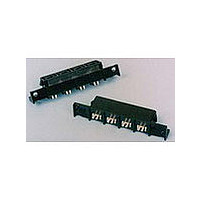
556881-4 TE Connectivity, 556881-4 Datasheet - Page 17

556881-4
Manufacturer Part Number
556881-4
Description
Power to the Board RCPT ASY VRT WTB 4 POS
Manufacturer
TE Connectivity
Type
Powerr
Datasheet
1.556881-4.pdf
(30 pages)
Specifications of 556881-4
Gender
F
Body Orientation
Straight
Number Of Contacts
4POS
Number Of Ports
1Port
Number Of Terminals
8
Contact Material
Copper Alloy
Voltage Rating Max
600VAC
Mounting Style
Through Hole
Termination Method
Solder
Contact Plating
Tin
Product Depth (mm)
14.43mm
Contact Gender
Socket (Female)
Number Of Positions / Contacts
4
Termination Style
Wire
Housing Material
Polyphenylene Sulfide
Product Type
Connector
Connector Type
Connector Assembly
Pcb Mounting Orientation
Vertical
Make First / Break Last
No
Pcb Mount Retention
Without
Termination Method To Pc Board
Through Hole - Solder
Pcb Mount Alignment
Without
Sealed
No
Ul File Number
E28476
Csa File Number
LR 7189
Mating Retention Type
Latching
Vde Tested
No
Contact - Rated Current (a)
35
Operating Voltage Reference
AC
Operating Voltage (vac)
600
Tail Length (mm [in])
4.9 [0.192]
Tail Orientation
In-line
Profile Height (y-axis) (mm [in])
12.70 [0.500]
Mating Retention
With
Number Of Positions
4
Centerline (mm [in])
11.18 [0.440]
Number Of Rows
1
Length (x-axis) (mm [in])
69.088 [2.720]
Width (z-axis) (mm [in])
19.30 [0.760]
Contact Base Material
Copper Alloy
Contact Type
Pin/Socket
Contact Design
Dual Beam
Contact Plating, Mating Area, Material
Tin
Contact Plating, Mating Area, Thickness (µm [?in])
3.81 [150]
Tail Plating Material
Tin
Tail Plating, Thickness (µm [?in])
2.54 [100]
Connector Style
Receptacle
Housing Color
Black
Mating Alignment
With
Mating Alignment Type
Polarization
Ul Flammability Rating
UL 94V-0
Custom Configurable
No
Rohs/elv Compliance
RoHS compliant, ELV compliant
Lead Free Solder Processes
Not relevant for lead free process
Rohs/elv Compliance History
Always was RoHS compliant
Agency/standard
UL, CSA
Ul Rating
Recognized
Ul Voltage Rating (vac)
600
Csa Certified
Yes
Operating Temperature (°c [°f])
0 – 105 [32 – 221]
Applies To
Printed Circuit Board
Pcb Thickness, Recommended (mm [in])
1.57 – 3.18 [0.062 – 0.1251]
Application Use
Wire-to-Board
Contact Transmits (typical Application)
Power
Packaging Method
Loose Piece
Lead Free Status / RoHS Status
Compliant
18
Catalog 1308885
Issued 3-05
www.tycoelectronics.com
Product Facts
I
I
I
I
I
I
I
I
I
I
I
Rated to 600 VAC (RMS)
Flame retardant housings
94V-0
Housings, adapters, and
power terminals keyed for
proper assembly
Stackable housings provide
easy wire routing and neat
wire dressing
Built-in interlocking fea-
tures better resist shock
and vibration
Usable as in-line connec-
tor, or as panel and surface
mount connector
Available in six different
colors for circuit coding
and identification
Choice of two power termi-
nals accommodates 10-12
AWG and 14-16-18 AWG
conductors
Recognized
under the
Component Program of
Underwriters Laboratories
Inc., File No. E28476
CSA Certified,
File No. LR7189
VDE Registered #5133
R
Dimensions are in inches and
millimeters unless otherwise
specified. Values in brackets
are metric equivalents.
R
Power Connectors for
Industrial and Commercial Applications
AMPINNERGY Wire-To-Wire Connectors
AMPINNERGY Wire-To-
Wire (WTW) Connectors
provide a reliable and effi-
cient means of intercon-
necting conductors
employed to carry up to
600 VAC in power circuits
or networks.
The WTW Connectors con-
sist of mating hermaphro-
ditic, flame retardant poly-
carbonate housings into
which customer terminated
power contacts are insert-
ed. Stackable in four direc-
tions through the use of
molded interlocking key-
ways, the connectors make
wire routing and dressing
orderly and easy to accom-
plish. More importantly, the
built-in interlocking features
on the connectors and the
accessory mounting
adapters provide better
resistance to the effects of
shock and vibration, keep-
ing the interconnect more
stable and secure.
The design features of the
WTW Connector make it
easily applicable to free
hanging, surface mounted
or panel mounted applica-
tions. By simply sliding the
accessory mounting
adapters into the molded
keyways of the connector
housing, a free hanging
Dimensions are shown for
reference purposes only.
Specifications subject
to change.
connector can be trans-
formed into a surface
mount connector or a
panel mount connector.
Customer supplied 8-32
screws and nuts may be
used to secure the connec-
tors configured with the
mounting adapters to print-
ed circuit boards or distri-
bution panels. The same
hardware may be used to
secure the connectors to
pre-cut openings in the
panels.
Furthermore, WTW
Connector housings,
mounting adapters and
power terminals are all pro-
vided with alignment or
keying features that make it
difficult to improperly
assemble and apply the
connector. Alignment slots
and tabs on the plastic
connector housings pro-
vide for easy mating of the
housings, even in the dark!
Mounting adapters have a
keyway on one side and a
key on the other side pro-
viding for easy assembly to
the connector by touch
alone if necessary. And the
power terminals have a
side tab that helps prevent
the incorrect insertion of
the terminated conductor
into the housing.
USA: 1-800-522-6752
Canada: 1-905-470-4425
Mexico: 01-800-733-8926
C. America: 52-55-5-729-0425
Once inserted, the con-
tacts firmly latch within the
connector housing.
The WTW Connector sys-
tem is available in six dif-
ferent and distinctive colors
which makes circuit differ-
entiation and identification
possible. The crimped
power terminals will
accommodate either 10-12
AWG or 14-16-18 AWG
stranded conductors.
Depending upon the con-
ductor size and the num-
ber of conductors in the
connector configuration,
the current rating ranges
from 10 amperes to 55
amperes.
Technical Documents
Product Specification
108-1373 AMPINNERGY WTW
Connectors
Application Specification
114-6051
Instruction Sheets
408-3277 AMPINNERGY Wire-To-Wire
Stackable Connectors
408-3198 Inspection of AMPINNERGY
System Power Contacts
South America: 55-11-3611-1514
Hong Kong: 852-2735-1628
Japan: 81-44-844-8013
UK: 44-141-810-8967


