1053354-1 TE Connectivity, 1053354-1 Datasheet - Page 2
1053354-1
Manufacturer Part Number
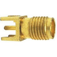
1053354-1
Description
RF/COAXIAL, SMA JACK, STR, 50OHM, SOLDER
Manufacturer
TE Connectivity
Type
SMAr
Datasheet
1.1053354-1.pdf
(24 pages)
Specifications of 1053354-1
Gender
F
Body Style
Straight
Terminate To
PCB
Mounting Style
Through Hole
Termination
Solder
Body Plating
Gold
Contact Plating
Gold
Contact Material
Beryllium Copper
Insulation Material
Polytetrafluoroethyl
Body Material
Stainless Steel
Product Height (mm)
9.5mm
Product Depth (mm)
6.3mm
Product Length (mm)
6.3mm
Connector Type
SMA Coaxial
Coaxial Termination
Solder
Impedance
50ohm
Frequency Max
12.4GHz
Rohs Compliant
Yes
Product Type
Connector - RF
Rf Connector Type
SMA
Pcb Mounting Orientation
Vertical
Body Finish
Gold
Center Contact
With
Captivated Contacts
With
Dielectric Material
PTFE Thermoplastic
Panel Mount Retention
Without
Snap-lock
Without
Length (mm [in])
9.53 [0.375]
Center Contact Material
Beryllium Copper
Center Contact Plating
Gold
Government/industry Qualification
No
Rohs/elv Compliance
RoHS compliant, ELV compliant
Lead Free Solder Processes
Wave solder capable to 240°C, Wave solder capable to 260°C, Wave solder capable to 265°C, Reflow solder capable to 245°C, Reflow solder capable to 260°C, Pin-in-Paste capable to 245°C, Pin-in-Paste capable to 260°C
Rohs/elv Compliance History
Always was RoHS compliant
Applies To
Printed Circuit Board
Lead Free Status / RoHS Status
Compliant


Specifications
General
Material
Finish
Design
Electrical
Insulation Resistance
Corona Level
Dielectric Withstanding Voltage
RF High Potential
Contact Resistance
VSWR
RF Leakage
Insertion Loss
Mechanical
Force to Engage
Coupling Nut Retention
Coupling Proof Torque
Cable Retention
Mating Characteristics
Connector Durability
Recommended Mating Torque
Environmental
Vibration
Shock
Thermal Shock
Corrosion (Salt Spray)
Moisture Resistance
Catalog 1307191
Revised 3-07
www.tycoelectronics.com
Dimensions are in millimeters
and inches unless otherwise
specified. Values in brackets
are standard equivalents.
Applicable Paragraph
MIL-C-39012
RF Coax Connectors
SMA Connectors
3.3.1
3.5.1
3.11
3.16
3.14
3.19
3.21
3.22
3.17
3.23
3.26
3.27
3.25
3.24
3.15
3.18
3.20
3.13
3.3
3.4
3.6
3.7
—
Steel corrosion resistant per ASTM-A-582 and ASTM-A-484, Type 303. Beryllium copper per
ASTM-B-196. PTFE Fluorocarbon per ASTM-D-1710.
Center contacts shall be gold plated to a min. thickness of .00127 [.00005] in accordance with
MIL-G-45204, ASTM-B-488. All other metal parts shall be finished as to provide a connector
which meets the corrosion requirements.
The design shall be such that the outline shown in this catalog and the interface dimensions of
MIL-STD-348A are met.
The insulation resistance shall not be less than 10,000 megohms.
Refer to applicable military slash sheet, product drawing or spec.
Refer to applicable military slash sheet, product drawing or spec.
Refer to applicable military slash sheet, product drawing or spec.
Refer to applicable military slash sheet, product drawing or spec.
Refer to applicable military slash sheet, product drawing or spec. Frequency range dependent on
cable used.
Refer to applicable military slash sheet, product drawing or spec.
Refer to applicable military slash sheet, product drawing or spec. Frequency range dependent on
cable used.
The torque required to engage and disengage shall not exceed 2 in.-lbs. The longitudinal force is
not applicable.
60 lbs. min. Applicable for plug connectors only.
15 in.-lbs. min. Applicable for plug connectors only.
Refer to applicable military slash sheet or consult factory.
Applicable to jack connectors only. Reference MIL-STD-348A for dimensions; oversize test pin
.953 [.0375] min. dia., .76 - 1.14 [.030-.045] deep, insertion force 3 lbs. max. with .940 [.0370]
min. dia. pin, withdrawal force 1 oz. min. with .902 [.0355] max. dia. pin.
The connector to be tested and its mating connector shall be subjected to 500 insertion and
withdrawal cycles at 12 cycles per minute max. The connector shall show no evidence of
mechanical failure and shall meet the mating characteristic requirements.
7 to 10 in.-lbs.
Specification MIL-STD-202, method 204, test condition D
Specification MIL-STD-202, method 213, test condition I
Refer to applicable military slash sheet or consult factory.
Specification MIL-STD-202, method 101, test condition B.
Specification MIL-STD-202, method 106. No measurements at high humidity. Insulation
resistance shall be at least 200 megohms within 5 minutes of removal from humidity.
Dimensions are shown for
reference purposes only.
Specifications subject
to change.
(Continued)
USA: 1-800-522-6752
Canada: 1-905-470-4425
Mexico: 01-800-733-8926
C. America: 52-55-1106-0803
South America: 55-11-2103-6000
Hong Kong: 852-2735-1628
Japan: 81-44-844-8013
UK: 44-8706-080-208
101
Related parts for 1053354-1
Image
Part Number
Description
Manufacturer
Datasheet
Request
R

Part Number:
Description:
RF/COAXIAL, BNC JACK, R/A, 75OHM, SOLDER
Manufacturer:
TROMPETER ELECTRONICS
Datasheet:

Part Number:
Description:
Printers THERMAL PRINTER HS-SLEEVE MARKER
Manufacturer:
TE Connectivity


Part Number:
Description:
High Speed / Modular Connectors 30P HEADER ASSY
Manufacturer:
TE Connectivity
Datasheet:

Part Number:
Description:
High Speed / Modular Connectors REC 6X005P R/A LT B-PLANE HS3
Manufacturer:
TE Connectivity
Datasheet:

Part Number:
Description:
High Speed / Modular Connectors 2MM HM RCPT 50P R/A AU
Manufacturer:
TE Connectivity
Datasheet:

Part Number:
Description:
High Speed / Modular Connectors 2MM HM RCPT 50P R/A AU
Manufacturer:
TE Connectivity
Datasheet:


Part Number:
Description:
Manufacturer:
TE Connectivity
Datasheet:


Part Number:
Description:
Manufacturer:
TE Connectivity
Datasheet:

Part Number:
Description:
Manufacturer:
TE Connectivity
Datasheet:

Part Number:
Description:
Manufacturer:
TE Connectivity
Datasheet: