903-369P-51A2 Amphenol, 903-369P-51A2 Datasheet - Page 13
903-369P-51A2
Manufacturer Part Number
903-369P-51A2
Description
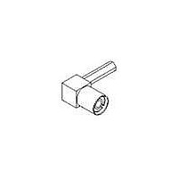
RF Connectors SMB (M) R/A M17/152 TRC
Manufacturer
Amphenol
Type
SMBr
Specifications of 903-369P-51A2
Gender
PL
Body Style
Right Angle
Terminate To
RG 316/U Cable
Mounting Style
Cable
Termination
Solder
Operating Temp Range
-65C to 165C
Operating Frequency
0 to 4
Body Plating
Nickel
Contact Plating
Gold
Contact Material
Beryllium Copper
Insulation Material
Tetrafluoroethylene
Body Material
Brass/Zinc
Product Height (mm)
15.9mm
Product Length (mm)
13.3mm
Impedance
50Ohm
Product
Connector
Rf Series
SMB
Shell Plating
Nickel
Termination Style
Solder
Cable Type
M17/152, RG-316U Double Braided 2x RG-188
Connector Type
Connectors - Cable
Maximum Frequency
10 GHz
Operating Temperature Range
- 65 C to + 165 C
Lead Free Status / RoHS Status
Compliant


SMB
75 ohm High Density Coaxial Connectors
Amphenol high density 75 ohm
903 Series SMB connectors
conform to the requirements of
MIL-C-39012 and the interface is
in compliance with MIL-STD-348.
Features/Benefits
• Broadband capability through
• Can easily be identified by their
• Guided entry sleeve for positive
• Closed entry contact to prevent
• Full range of high density SMB
• Series gives design engineers
Amphenol Corporation Tel: 800-627-7100
4 GHz combines with
compact, space saving design.
red Teflon insulators.
mating.
"slide-by".
connector configurations is
available, including end launch,
printed circuit board and cable
connectors.
options in applications where
physical space is limited.
DEPENDING ON CONTACT
ELECTRICAL
MATERIAL
SPECIFICATIONS
PLUG
Impedance
Frequency range
Voltage rating
for RG-188/U cables
Dielectric
withstanding voltage
VSWR
straight
right angle
connectors
Contact resistance
Insulation resistance:
RF leakage
Insertion loss:
straight
rt. angle
Bodies
Center contacts
Outer contact
Crimp ferrules
Insulators
SPRING IS OPTIONAL
REFERENCE PLANE
DESIGN
.027 CONTACT
.045 MAX.
47
75 ohms
0-4 GHz with low
reflection
Sea level: 335 volts
70,000 ft: 85 volts
750 VRMS, RG-196 type
1000 VRMS, RG-188 type
735A type
1.25 + .04 f (GHz)
1.35 + .04 f (GHz)
Center contact:
initial, 6.0 milliohms;
After environmental, 8.0
Outer contact:
initial, 1.0 milliohms;
After environmental, 1.5
Braid to body:
initial, 1.0 milliohms;
After environmental, N/A
1000 megohms min.
-55 dB min. @ 2 - 3 GHz
0.30 dB @ 1.5 GHz
0.60 dB @ 1.5 GHz
Brass per QQB-626 or
zinc per ASTM B86-71,
as specified, nickel (or
gold) plated as listed
beryllium copper,
gold plated
Nickel or gold plated
as listed.
Annealed copper alloy
TFE - Red for I.D.
.007
.117
MIN.
MAX.
.089
CLOSED ENTRY
CONTACT
* These characteristics are typical and may not apply
MECHANICAL
ENVIRONMENTAL
to all connectors.
Mating
Engagement
forces
Connector affixment
to cable
Cable affixment to
center contact
Contact captivation
Cable retention
Connector durability
Temperature range
Thermal shock
Vibration
Shock
Corrosion
REF. PLANE
JACK
MAX.
.117
MIN.
.086
Amphenol
MIN.
75 ohm snap-on
coupling,
per MIL-STD-348
Initial 14 lbs. max.
engagement.
After 500 matings, 14 lbs.
max engagement and
disengagement.
2 lbs. min.
disengagement.
Braid and jacket:
hex crimp.
Solder or crimp
All types, except
as noted
Equal to breaking
strength of cable
employed
500 mating and
unmating cycles min.
.090
-65°C to + 165°C
MIL-STD-202 method
107 (test cond. B)
except high temp test
@ + 200°C
MIL-STD-202 method
204, snap-on (test
cond. B) (15G's)
MIL-STD-202 method
213, snap-on (test
cond. B) 75 G's @ 6
milliseconds 1/2 sine.
MIL-STD-202 method
101 (test cond. B)
5% salt solution.
www.amphenolrf.com
®
Related parts for 903-369P-51A2
Image
Part Number
Description
Manufacturer
Datasheet
Request
R

Part Number:
Description:
RF Connectors RIGHT ANGLE PLUG
Manufacturer:
Amphenol
Datasheet:

Part Number:
Description:
Terminals LUG LOCKING TINNED#4
Manufacturer:
Keystone Electronics
Datasheet:

Part Number:
Description:
Cable Specification: PU CABLE, UL20549 24AWG*8C+AD,OD= 6.0mm
Manufacturer:
Amphenol
Part Number:
Description:
BEN44-104-10005-2 5 WAY 44 RECEPTACLE INSULATOR
Manufacturer:
Amphenol