1981568-1 TE Connectivity, 1981568-1 Datasheet - Page 51
1981568-1
Manufacturer Part Number
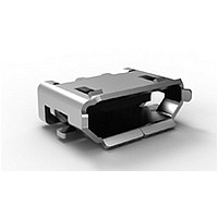
1981568-1
Description
REC TYPE B ASSY (AU) MICRO USB
Manufacturer
TE Connectivity
Series
DisplayPort Receptacles and Cable Assembliesr
Datasheet
1.1981568-1.pdf
(116 pages)
Specifications of 1981568-1
Number Of Contacts
5POS
Body Orientation
Right Angle
Contact Material
Copper Alloy
Operating Temp Range
-55C to 85C
Current Rating (max)
1/ContactA
Voltage Rating Max
30VAC
Product Height (mm)
3mm
Number Of Ports
1Port
Gender
RCP
Mounting Style
Surface Mount
Contact Plating
Gold Over Nickel
Housing Material
Thermoplastic
Product
Micro USB Type B Connectors
Standard
USB
Pitch
0.65 mm
Current Rating
1 A
Termination Style
Solder Pad
Connector Type
Micro USB Type B Receptacle
Color
Black
Features
Without Locking Feature
Flammability Rating
UL 94 V-0
Insulation Resistance
100 MOhms
Mounting Angle
Right
Number Of Positions / Contacts
5
Operating Temperature Range
0 C to + 50 C
Voltage Rating
30 VAC
Size
Micro
Orientation
Right Angle
Mount Location
Top
Termination Method
Surface Mount
Locking Feature
Without
Led
Without
Panel Ground
Without
Pcb Mount Retention Type
SMT Hold Down
Shell Plating
Reflowed Tin over Nickel
Assembly Process Feature
Without Pick and Place Cover
Locating Post(s)
Without
Number Of Positions
5
Contact Termination Type
Surface Mount
Contact Plating, Mating Area, Material
Gold
Contact Plating, Mating Area, Thickness (µm [?in])
0.762 [30]
Housing Color
Black
Industry Standard
USB 2.0
Rohs/elv Compliance
RoHS compliant, ELV compliant
Lead Free Solder Processes
Reflow solder capable to 245°C
Rohs/elv Compliance History
Always was RoHS compliant
Usb-if Test Id Number (tid)
60001336
Applies To
Printed Circuit Board
Pcb Thickness, Recommended (mm [in])
1.00 [0.039]
Packaging Method
Tape & Reel
Lead Free Status / RoHS Status
Compliant
Available stocks
Company
Part Number
Manufacturer
Quantity
Price
Company:

Part Number:
1981568-1
Manufacturer:
TE/AMP
Quantity:
30 000
Company:
Part Number:
1981568-1
Manufacturer:
TE
Quantity:
20 000


STAX elastomers are com-
posed of alternating layers of
conductive and non-conduc-
tive silicone rubber. Silicone
rubber is the base material
because it has excellent aging
properties, chemical stability,
electrical reliability, and super-
ior performance in shock and
vibration. It also provides a
gasket-like seal to protect the
contact surfaces.
The conductive layers consist
of tiny metallic particles
dispersed in silicone rubber.
Within each of the conductive
layers, the metallic particles
create thousands of conduc-
tive paths. Therefore, each
conductive layer provides
multiple points of contact at
the substrate interface. While
the conductive layers ensure
contact between mating pads,
the non-conductive layers
isolate the conductive layers
from each other. The alter-
nating STAX construction,
200 conductive layers per inch
(8 per mm), allows multiple
conductive layers to make
contact to a single contact
pad while the non-conductive
layers electrically isolate
adjacent contact pads.
The advantage of this material
construction is that you
achieve 3–4 conductive layers
typically making contact to a
single contact pad on the
board. A single elastomeric
strip (element) is used to con-
nect an entire row of contacts.
The multiple layers coupled
with the thousands of con-
ductive paths in each layer
ensure reliable interconnect.
Why use a
Tyco Electronics
Elastomeric Connector
1 – Simple Implementation
Assembly is easy as making
a sandwich. There is no
soldering, no special tooling
or machinery.
2 – Easily Modified
How often is a standard off-
the-shelf connector ideal for
Products for Mobile Equipment
Connectors
STAX™ LD Elastomeric Connectors
your application? Smaller
height, higher I/O, greater cur-
rent capacity, lower resistance,
less PCB area are all modifi-
cations that can be made.
3 – Fast
The flexible elastomeric manu-
facturing process allows quick
turn on prototypes (1 week)
to test solutions and rapid
ramp on production. Proto-
types are made with the same
process as production.
4 – No Tooling
An elastomer-only approach
allows the customer to imple-
ment the housing and align-
ment features within existing
plastic or metal structure.
Modifications of elastomer
length, height, and width do
not require tooling.
5 – Reliability
Tyco Electronics elastomeric
products have been tested to
the following:
• MIL STD-1344
• IEC-68-2
• EIA-364
• MIL STD-202
• JIS C 0020
• JEIDA 38
• INTEL SPEC 5.1, 5.2
• NUMEROUS CUSTOMER
Test data available on request.
6 – Product Support
Tyco Electronics product
engineers work directly with
customer engineering teams
on modifications and custom
solutions for volume applica-
tions. All aspects of the design
and implementation of the
product are reviewed to ensure
a successful product launch.
Custom Capability
Application requirements vary
dramatically across the many
industries that elastomers are
used. The technology is
flexible in adapting to many
of these requirements but, as
with any product, there are
limits.
All specifications subject to change. Consult Tyco Electronics for latest specifications.
ACCELERATED LIFE
TESTING (ALT)
1. Determine if an
a) Board-Board separation
b) X-YAlignment (>±0.25 mm)?
c) Sliding Contact?
d) Contact Pitch: <0.8 mm?
2. Determine if “holder”
Elastomeric Connector
is appropriate for the
Application
> 8.0 mm?
An elastomer cost is tied
closely to material usage
(precious metals). In appli-
cation greater than 8 mm
elastomers lose their price
competitiveness.
Unlike a mechanical male-
female connector an elas-
tomer cannot perform the
alignment of the system.
The reference drawings
show how pins can provide
satisfactory alignment.
Other methods can achieve
the same result.
Silicone by the nature of
the product has a high co-
efficient of friction. Sliding a
contacting surface across
the elastomer will not be
reliable.
Since an elastomeric con-
nector depends on the align-
ment of the mating surfaces
by an external means, con-
tact pitch <0.8 mm is not
easily achievable. However,
board real-estate is minimi-
zed by achieving more
closely-spaced rows of con-
tacts pads than fine-pitch
connectors.
functions can be inte-
grated within existing
structure?
The holder is synonymous
with the plastic that sur-
rounds traditional mecha-
nical connectors. The most
efficient and cost effective
way to implement a STAX
connector is by incorpora-
ting a retaining slot into an
existing housing or board
separator as shown on the
reference designs.
In an approved application,
Elastomeric Technologies
(continued)
3. Can Tyco Electronics
Below are examples of
complete connection solutions
in challenging applications.
Circular Connector Grafted
160 Pos. (LCP Frame)
Ultra-Low Profile Inmolded
8 Pos. 0.5 mm Height Silicone
Rubber Base
Module-to-Board Grafted
220 Pos. Peripheral Contact
Ultem Frame
application engineers are
avail-able to assist in:
• Defining customer furnish-
• Providing design input for:
•
•
•
•
supply a complete
Connector Solution?
Yes. These solutions can
take the form of simple
holders with STAX connec-
tors held in place by:
• Localized interference
• In-molding
• Grafting
The holder or frame can be
plastic, silicone rubber, or
metal and typically has low
tooling investment:
ed housing requirements.
■
■
■
■
Alignment
Deflection
Pad layout
Final elastomer dimen-
sions
Catalog 1654270-2
Revised 8-2007
49
Related parts for 1981568-1
Image
Part Number
Description
Manufacturer
Datasheet
Request
R

Part Number:
Description:
Printers THERMAL PRINTER HS-SLEEVE MARKER
Manufacturer:
TE Connectivity


Part Number:
Description:
High Speed / Modular Connectors 30P HEADER ASSY
Manufacturer:
TE Connectivity
Datasheet:

Part Number:
Description:
High Speed / Modular Connectors REC 6X005P R/A LT B-PLANE HS3
Manufacturer:
TE Connectivity
Datasheet:

Part Number:
Description:
High Speed / Modular Connectors 2MM HM RCPT 50P R/A AU
Manufacturer:
TE Connectivity
Datasheet:

Part Number:
Description:
High Speed / Modular Connectors 2MM HM RCPT 50P R/A AU
Manufacturer:
TE Connectivity
Datasheet:


Part Number:
Description:
Manufacturer:
TE Connectivity
Datasheet:


Part Number:
Description:
Manufacturer:
TE Connectivity
Datasheet:

Part Number:
Description:
Manufacturer:
TE Connectivity
Datasheet:

Part Number:
Description:
Manufacturer:
TE Connectivity
Datasheet: