GJM1555C1H1R0CB01D Murata, GJM1555C1H1R0CB01D Datasheet - Page 5
GJM1555C1H1R0CB01D
Manufacturer Part Number
GJM1555C1H1R0CB01D
Description
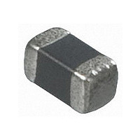
CAPACITOR, NP0, 0402, 1PF
Manufacturer
Murata
Specifications of GJM1555C1H1R0CB01D
Tolerance (+ Or -)
0.25pF
Voltage
50VDC
Temp Coeff (dielectric)
C0G
Operating Temp Range
-55C to 125C
Mounting Style
Surface Mount
Construction
SMT Chip
Case Style
Ceramic Chip
Failure Rate
Not Required
Wire Form
Not Required
Product Length (mm)
1mm
Product Depth (mm)
0.5mm
Product Height (mm)
0.5mm
Product Diameter (mm)
Not Requiredmm
Capacitance
1pF
Package / Case
0402
Capacitance Tolerance
± 0.25pF
Voltage Rating
50VDC
Capacitor Dielectric Type
Ceramic Multi-Layer
Capacitor Case Style
0402
No. Of Pins
2
Lead Spacing
0.3mm
Operating Temperature
RoHS Compliant
Operating Temperature Range
-55°C To +125°C
Svhc
No SVHC (15-Dec-2010)
Rohs Compliant
Yes
Lead Free Status / RoHS Status
Compliant
Available stocks
Company
Part Number
Manufacturer
Quantity
Price
Company:

Part Number:
GJM1555C1H1R0CB01D
Manufacturer:
MURATA
Quantity:
640 000


10 – Innovator in Electronics
A p p l i c At i o n S p e c i F i c c A pA c i t o r S
High Frequency Ceramic Capacitors
GJM Specifications and Test Methods
Item
Operating Temperature
Appearance
Dimension
Dielectric Strength
Insulation Resistance
Q
Adhesive Strength of
Termination
Vibration Resistance
Deflection
Solderability of Termination
Resistance to Soldering Heat
Temperature Cycle
Humidity Steady State
Humidity Load
Specifications and Test Methods
Capacitance
Temperature
Characteristics
Temperature Coefficent:
Within the specified tolerance. (Table A-1)
Capacitance Change: Within ±0.2% or ±0.05pF
(Whichever is larger)
Specifications
-55 C to 125 C
No defects or abnormalities.
Within the specified dimensions.
No defects or abnormalities.
More than 10,000M or 500 ·F
(Whichever is smaller)
30pFmin.: Q
30pFmax.: Q
C: Nominal Capacitance(pF)
No removal of the terminations or other defect should
occur.
Appearance: No defects or abnormalities.
Capacitance: Within the specified tolerance.
30pFmin.: Q
30pFmax.: Q
C: Nominal Capacitance(pF)
No crack or marked defect should occur.
75% of the terminations are to be soldered evenly
and continuously.
Appearance: No marking defects.
Capacitance Change: Within ±2.5% or
± 0.25 pF (Whichever is larger)
30pFmin.: Q
30pFmax.: Q
C: Nominal Capacitance(pF)
Appearance: No marking defects.
Capacitance Change: Within ±2.5% or
± 0.25 pF (Whichever is larger)
30pFmin.: Q
30pFmax.: Q
C: Nominal Capacitance (pF)
Appearance: No marking defects.
Capacitance Change: Within ±5% or
± 0.5pF (Whichever is larger)
30pF and over: Q
10pF and over, 30pF and below: Q 275+5C/2
10pF and below: Q
C: Nominal Capacitance (pF)
Appearance: No marking defects.
Capacitance Change: Within ±7.5% or ±0.75pF
(Whichever is larger)
1000
1000
1000
1000
400+20C
400+20C
400+20C
400+20C
w
350
200+10C
w
w
.
m
u
r
a
t
Test Methods
Reference temperature: 25 C
Visual inspection.
Using calipers.
300% of the rated voltage
DC voltage not exceeding the rated voltage at 25°C
and 75%RH max. and within 2 minutes of charging.
Frequency 1±0.1MHz
Voltage 0.5 to 5Vrms
Solder the capacitor to the test jig (glass epoxy
board) shown in Fig.1a using a eutectic solder. Then
apply 5N* force in parallel with the test jig for
10±1sec. *2N(GJM03)
The frequency range, from 10 to 55Hz and return to
10Hz, should be traversed in approximately 1 minute.
This motion should be applied for a period of 2 hours
in each 3 mutually perpendicular directions (total of 6
hours).
Flexure:1mm
Immerse in eutectic solder solution for 2±0.5 seconds
at 230±5°C or Sn-3.0Ag-0.5Cu solder solution for
2±0.5 seconds at 245±5°C .
Immerse the capacitor in a eutectic solder solution or
Sn-3.0 Ag–0.5Cu solder solution at 270±5°C for
10±0.5 seconds. Let sit at room temperature for 24±2
hours.
−55°C to 125°C Five cycles
40±2°C and 90 to 95% humiduty for 500±12 hours.
Apply the rated voltage at 40±2°C and 90 to 95%
The capacitance change should be measured after
5 min. at each specified temperature stage. The
temperature coefficient is determined using the
capacitance measured in step 3 as a reference.
When cycling the temperature sequentially from step 1
through 5 the capacitance should be within the
specified tolerance for the temperature coefficient and
capacitance change as in Table A-1. The capacitance
drift is calculated by dividing the differences between
the maximum and minimum measured values in steps
1, 3 and 5 by the cap. value in step 3.
Step
a
1
2
3
4
5
.
c
o
m
Temperature ( C)
125 3
-55 3
25 2
25 2
25 2
GJM Series
C-29-C
Related parts for GJM1555C1H1R0CB01D
Image
Part Number
Description
Manufacturer
Datasheet
Request
R

Part Number:
Description:
Murata Microblower 20x20 DCDC Driver Board - Samples Only
Manufacturer:
Murata
Part Number:
Description:
357-036-542-201 CARDEDGE 36POS DL .156 BLK LOPRO
Manufacturer:
Murata
Datasheet:
Part Number:
Description:
Manufacturer:
Murata
Datasheet:
Part Number:
Description:
Manufacturer:
Murata
Datasheet:
Part Number:
Description:
Manufacturer:
Murata
Datasheet:
Part Number:
Description:
Manufacturer:
Murata
Datasheet:
Part Number:
Description:
Manufacturer:
Murata
Datasheet:
Part Number:
Description:
Manufacturer:
Murata
Datasheet:
Part Number:
Description:
Manufacturer:
Murata
Datasheet:
Part Number:
Description:
BLM21BD751SN1On-Board Type (DC) EMI Suppression Filters
Manufacturer:
Murata
Datasheet:
Part Number:
Description:
BLM15AG100SN1On-Board Type (DC) EMI Suppression Filters
Manufacturer:
Murata
Datasheet:
Part Number:
Description:
NFE31PT222Z1E9On-Board Type (DC) EMI Suppression Filters
Manufacturer:
Murata
Datasheet:
Part Number:
Description:
Chip Coil
Manufacturer:
Murata
Datasheet:
Part Number:
Description:
Chip Coil
Manufacturer:
Murata
Datasheet: