603-2 TELEDYNE, 603-2 Datasheet

Solid State Relays 32VDC 36mA PNL MT

603-2

Manufacturer Part Number
603-2
Description
Solid State Relays 32VDC 36mA PNL MT
Manufacturer
TELEDYNE
Datasheet

Specifications of 603-2

Application
For fast switching speed
Brand/series
603 Series
Current, Rating
5 A
Dielectric Strength
1500 VAC (Min.)
Dimensions
2.02 in. (Max.) L x 1 in. W x 0.9 in. H
Function
General Purpose
Mounting Type
Panel
Relay Type
Solid State
Resistance, Thermal, Junction To Case
10 °C⁄W
Temperature, Ambient, Maximum
80 °C
Temperature, Ambient, Minimum
-40 °C
Termination
Screw
Voltage, Control
32 VDC
Voltage, Rating
50 VDC

Available stocks

Company
Part Number
Manufacturer
Quantity
Price
Company:
Part Number:
603-25-150/BLK
Quantity:
302
© 2002 TELEDYNE RELAYS
Part Number
603-1
603-2
603-3
603-4
(22.10)
Figure 1 – 603 relays; dimensions in inches (mm)
0.87
Weight: 3 oz. (85.05g)
Tolerances ± 0.015 (0.38) unless otherwise specified
1.00 (25.40)
(15.24)
(15.24)
(15.24)
MECHANICAL SPECIFICATION
0.60
0.60
0.60
0.25 (6.35) TY P.
# 6 Binder
HD Screw
Description
2A, 50Vdc optically isolated
solid-state relay
5A, 50Vdc optically isolated
solid-state relay
5A, 250Vdc high-voltage, transformer
isolated solid-state relay
5A, 250Vdc high-voltage, transformer
isolated solid-state relay
MAX.
# 6 Screw
Mtg. Hole
2.02
0.250 (6.35)
Quick
Disconnect
Terminal
Antirotation Boss On Vertical Center Line
(3810)
1.500
1.680 (42.67)
1.740 (44.20)
(22.86)
0.90
0.375
(9.52)
MIN.
0.032
(0.81) DIA.
0.031 (0.79)
(19.05)
0.750
1.25 (31.75)
(800) 284-7007 • www.teledynerelays.com
MAX.
0.06 (1.52) MAX.
0.110
(2.79) DIA.
FEATURES
• Fast Switching Speed: Where speed is important
• Floating Output: Eliminates ground loops and
• Low Off-State Leakage Current: High offstate
• High Dielectric Strength: For safety and
DESCRIPTION
The 603-1 and 603-2 optically coupled solid-state
relays are rated at 2 Adc and 5 Adc at 50 Vdc,
and are available with TTL compatible inputs.
Packages are available in three different
configurations with a choice of screw terminals,
quick disconnect terminals or through hole solder
pins. This allows for maximum flexibility for
mounting onto printed circuit boards, panels, or
heat sink mounting with optimal mechanical and
thermal considerations.
The 603-3 and 603-4 relays were designed
specifically for high-voltage loads up to 5A at 250
Vdc. They utilize a Teledyne transformer coupled
driver/isolator to provide high input/output isolation
and low offstate leakage. The adaptive package
design offers a choice of screw or quick
disconnect terminals for chassis, panel, or heat
sink mounting, and solder pins for direct mounting
on PC boards.
signal-level ground noise.
impedance
protection of signal-level circuits.
* Input and output polarity must be observed.
Inductive loads must be diode suppressed.
+
WIRING DIAGRAM
2A and 5A/50Vdc and 5A/250 Vdc
Figure 2
DC Solid-State Relays
Series 603
+
*
603\072002\Q1
603 9

Related parts for 603-2

603-2 Summary of contents

Page 1

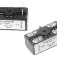
... High Dielectric Strength: For safety and protection of signal-level circuits. 0.06 (1.52) MAX. 0.110 (2.79) DIA. DESCRIPTION The 603-1 and 603-2 optically coupled solid-state 0.750 relays are rated at 2 Adc and 5 Adc at 50 Vdc, (19.05) and are available with TTL compatible inputs. Packages are available in three different ...

Page 2

... On-State Voltage Drop 603-1, -2 Vdc 603-3, -4 Vdc Output Leakage Current Vdc 603-1 (25°C) 603-2 (25°C) 0.8 Vdc 603-3, 603-4 (25°C) 0.4 Vdc 603-3, 603-4 (100°C) Turn-On Time –32 Vdc 603-1, -2 603-3, -4 Turn-Off Time 603-1, -2 Max Units 603-3, -4 ...

Page 3

... Ambient Temperature (˚C) Figure 7 – 603-3, -4 load current vs. temperature © 2002 TELEDYNE RELAYS CHARACTERISTICS CURVES 6 Mounted on 1.3˚C/W heat sink (see note Figure 4 – 603-2 load current vs. temperature 500 400 300 200 100 0.01 0 Figure 6 – 603-1, -2 maximum surge as function of load voltage 603-3 ...

Related keywords