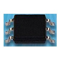
OPIA6010ATUA Optek, OPIA6010ATUA Datasheet - Page 2

OPIA6010ATUA
Manufacturer Part Number
OPIA6010ATUA
Description
Transistor Output Optocouplers 50mA 60-600CRT%
Manufacturer
Optek
Datasheet
1.OPIA6010ATRA.pdf
(23 pages)
Specifications of OPIA6010ATUA
Maximum Fall Time
20 us
Maximum Input Diode Current
50 mA
Maximum Reverse Diode Voltage
6 V
Maximum Rise Time
20 us
Output Device
Phototransistor
Configuration
1 Channel
Input Type
DC
Maximum Collector Emitter Voltage
60 V
Maximum Collector Emitter Saturation Voltage
0.3 V
Isolation Voltage
5000 Vrms
Current Transfer Ratio
600 %
Maximum Forward Diode Voltage
1.4 V
Maximum Collector Current
50 mA
Maximum Power Dissipation
200 mW
Maximum Operating Temperature
+ 125 C
Minimum Operating Temperature
- 55 C
Package / Case
SMD-6
Lead Free Status / RoHS Status
Lead free / RoHS Compliant
Available stocks
Company
Part Number
Manufacturer
Quantity
Price
Company:
Part Number:
OPIA6010ATUA
Manufacturer:
SIL
Quantity:
7 242
OPIA500B, OPIA4N35, OPIA4N33
OPIA2110, OPIA2210, OPIA5010, OPIA6010
SMD and SOP Packages
Package Outline Dimensions and Schematics: Top-View
Issue A.6
Page 2 of 23
Symbol
Part Number
Part Number
OPIA4N35A
OPIA4N33A
OPIA5010A
OPIA2210A
OPIA6010A
OPIA2110A
OPIA500B
Packaging
OPIA4N35
OPIA4N33
OPIA5010
OPIA2210
OPIA6010
OPIA2110
OPIA500
A
Sensor
LED
5/10
Definition
Anode
OPTEK reserves the right to make changes at any time in order to improve design and to supply the best product possible.
A-K
Isolation Voltage
A
A
A
A
A
A
1
A = Anode
B = Base
Max. (Vrms)
Part Number Suffix:
Symbol
3,750
5,000
5,000
5,000
5,000
5,000
5,000
K-A
K
K
K
K
K
2
B
Analog Output Devices Ordering Information
3
K
Definition
Pin #
Base
Phone: (972) 323-2200 or (800) 341-4747
E
E
E
E
E
E
E
K = Cathode
C = Collector
4
600 / - / 9,000
500 / 4,000 / -
Min/Typ/Max
60 / - / 600
50 / - / 600
50 / - / 600
40 / - / 400
19 / - / 50
LED Identification—Sensor Identification
TU = Ship in Tubes
Symbol
CTR
C
C
C
C
C
C
C
5
Configuration: Definition of Terms
C
B
B
B
B
B
B
6
Definition
Collector
LH-HL 0.8 / 0.8 (1.9K)
E = Emitter
Typ. Tr / Tf (µs)
R
L
= 100 ohms
Symbol
60 / 50
TR = Tape and Reel
5 / 60
5 / 4
2 / 3
2 / 3
4 / 3
OPTEK Technology Inc. — 1645 Wallace Drive, Carrollton, Texas 75006
E
FAX: (972) 323-2396 sensors@optekinc.com www.optekinc.com
Definition
Emitter
(Dar) = Photo Darlington
6-Pin SMD
6-Pin SMD
6-Pin SMD
6-Pin SMD
6-Pin SMD
6-Pin SMD
5-Pin SOP
Package
Symbol
K
Definition
Cathode
Example: OPI4N35ATRE
A K—B C E (Dar)
A K—B C E (Dar)
A K, K A—B C E
Configuration
Package Style B
Package Style A
A K—B C E
A K—B C E
AK—KCE
A K—C E
OPIA500
OPIA60X
(SMD)
(SOP)


