OPB705 Optek, OPB705 Datasheet
OPB705
Specifications of OPB705
Available stocks


Related parts for OPB705


OPB705 Summary of contents
Page 1
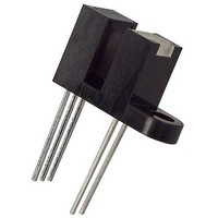
... Focused for maximum sensitivity Description: The OPB703, OPB704 and OPB705 consist of an Infrared (890nm) Light Emitting Diode (LED) and a NPN silicon Phototransistor, mounted side-by-side on converging optical axes in a black plastic housing and are designed for PCBoard mounting. The OPB703WZ, OPB704WZ, OPB705WZ and OPB70BWZ are designed for remote mounting utilizing interconnect wires of UL approved 26 AWG, 24” ...
Page 2
... Reflective Object Sensor OPB703 through OPB705, OPB703WZ through OPB705WZ, OPB70AWZ through OPB70FWZ OPB703WZ, OPB704WZ, OPB705WZ, OPB70AWZ, OPB70BWZ, OPB70CWZ, OPB70DWZ OPTEK reserves the right to make changes at any time in order to improve design and to supply the best product possible. Issue B.3 03/09 Page OPB703, OPB704, OPB705 ...
Page 3
... Reflective Object Sensor OPB703 through OPB705, OPB703WZ through OPB705WZ, OPB70AWZ through OPB70FWZ OPTEK reserves the right to make changes at any time in order to improve design and to supply the best product possible. OPTEK Technology Inc. — 1645 Wallace Drive, Carrollton, Texas 75006 Phone: (972) 323-2200 or (800) 341-4747 ...
Page 4
... RMA flux is recommended. Duration can be extended to 10 seconds maximum when flow soldering. (2) For OPB703, OPB704 and OPB705, derate linearly 1.67 mW/° C above 25° C. (3) For OPB703WZ, OPB704WZ, OPB705WZ, OPB70BWZ, OPB704G and OPB704GWZ derate linearly 1.82 mW/° C above 25° C. (4) The distance from the assembly face to the reflective surface is d. ...
Page 5
... Reflective Object Sensor OPB703 through OPB705, OPB703WZ through OPB705WZ, OPB70AWZ through OPB70FWZ (T Electrical Characteristics A (OPB70AWZ) SYMBOL PARAMETER Input Diode (See OP265 for additional information — for reference only) V Forward Voltage F I Reverse Current R Output PhotoDarlington (See OP535 for additional information — for reference only) ...
Page 6
... RMA flux is recommended. Duration can be extended to 10 seconds maximum when flow soldering. (2) For OPB703, OPB704 and OPB705, derate linearly 1.67 mW/° C above 25° C. (3) For OPB703WZ, OPB704WZ, OPB705WZ and OPB70BWZ, derate linearly 1.82 mW/° C above 25° C. (4) The distance from the assembly face to the reflective surface is d. ...
Page 7
... Notes: (1) RMA flux is recommended. Duration can be extended to 10 seconds maximum when flow soldering. (2) For OPB703WZ, OPB704WZ, OPB705WZ and OPB70BWZ, derate linearly 1.82 mW/° C above 25° C. (3) The distance from the assembly face to the reflective surface is d. (4) Lower curve is based on a calculated worst-case condition, rather than the conventional -2Ω limit. ...
Page 8
... CX Notes: (1) RMA flux is recommended. Duration can be extended to 10 seconds maximum when flow soldering. (2) For OPB703WZ, OPB704WZ, OPB705WZ and OPB70BWZ, derate linearly 1.82 mW/° C above 25° C. (3) The distance from the assembly face to the reflective surface is d. (4) Crosstalk ( the collector current measured with the indicated current in the input diode and with no reflecting surface. ...
Page 9
... Reflective Object Sensor OPB703 through OPB705, OPB703WZ through OPB705WZ, OPB70AWZ through OPB70FWZ OPB703—Output Distance OPB703 - Output vs Distance 1.8 Normalized Distance = 0.15" & Kodak 90% 1.6 1.4 1.2 1.0 0.8 0.6 0.4 0.2 0.0 0.0 0.1 0.2 0.3 0.4 0.5 Distance (inches) OPB705, OPB70A, OPB70C, OPB70D— ...