XR21V1412IL-0B-EB Exar Corporation, XR21V1412IL-0B-EB Datasheet - Page 5
XR21V1412IL-0B-EB
Manufacturer Part Number
XR21V1412IL-0B-EB
Description
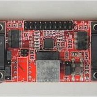
Interface Modules & Development Tools For XR21V1412 QFN32 USB, RS232;No Cables
Manufacturer
Exar Corporation
Series
-r
Specifications of XR21V1412IL-0B-EB
Interface Type
RS-232, USB
Operating Supply Voltage
3.3 V
Product
Interface Modules
Silicon Core Number
XR21V1412
Application Sub Type
UART
Kit Contents
Board
Main Purpose
Interface, USB 2.0 to UART
Embedded
No
Utilized Ic / Part
XR21V1412IL
Primary Attributes
-
Secondary Attributes
-
Silicon Manufacturer
Exar
Kit Application Type
Communication & Networking
For Use With/related Products
XR21V1412
Lead Free Status / Rohs Status
Lead free / RoHS Compliant


REV. 1.1.0
Pin Description
USB Interface Signals
I2C Interface Signals
GPIOB2/DSRB#
GPIOB3/DTRB#
GPIOB4/CTSB#
GPIOB5/RTSB#
GPIOB1/CDB#
USBD+
USBD-
N
SDA
SCL
AME
32-QFN
P
21
20
19
18
17
30
29
25
26
IN
#
T
OD
I/O
I/O
I/O
I/O
I/O
I/O
I/O
YPE
I
UART Channel B general purpose I/O or UART Carrier-Detect input (active low).
This pin has an internal pull-up resistor which is disabled during suspend mode. If
using this GPIO as an input, an external pull-up resistor is required to minimize the
power consumption in the suspend mode.
UART Channel B general purpose I/O or UART Data-Set-Ready input (active low).
See ”Section 1.5.5, Automatic DTR/DSR Hardware Flow Control” on
page 11.
mode. If using this GPIO as an input, an external pull-up resistor is required to mini-
mize the power consumption in the suspend mode.
UART Channel B general purpose I/O or UART Data-Terminal-Ready output (active
low).
on page 11.
pend mode. If using this GPIO as an input, an external pull-up resistor is required to
minimize the power consumption in the suspend mode.
UART Channel B general purpose I/O or UART Clear-to-Send input (active low).
See ”Section 1.5.4, Automatic RTS/CTS Hardware Flow Control” on
page 10.
mode. If using this GPIO as an input, an external pull-up resistor is required to mini-
mize the power consumption in the suspend mode.
UART Channel B general purpose I/O or UART Request-to-Send output (active low).
See ”Section 1.5.4, Automatic RTS/CTS Hardware Flow Control” on
page 10.
mode. If using this GPIO as an input, an external pull-up resistor is required to mini-
mize the power consumption in the suspend mode.
USB port differential data plus. This pin has a 1.5 K Ohm internal pull-up resistor.
USB port differential data minus.
I
be used to store default configurations upon power-up including the USB Vendor ID
and Device ID. See
required.
If an EEPROM is not used, this pin can be used with the SCL pin to select the
Remote Wake-up and Power modes. An external pull-up or pull-down resistor is
required. See
I
store default configurations upon power-up including the USB Vendor ID and Device
ID. See
If an EEPROM is not used, this pin can be used with the SDA pin to select the
Remote Wake-up and Power modes. An external pull-up or pull-down resistor is
required. See
2
2
C-controller data input/output (open-drain). An optional external I
C-controller serial input clock. An optional external I
See ”Section 1.5.5, Automatic DTR/DSR Hardware Flow Control”
Table 3
This pin has an internal pull-up resistor which is disabled during suspend
This pin has an internal pull-up resistor which is disabled during suspend
This pin has an internal pull-up resistor which is disabled during suspend
Table 2
Table 2
This pin has an internal pull-up resistor which is disabled during sus-
. A pull-up resisitor (typically 4.7 to 10 KOhms) is required.
Table 3
.
.
5
. A pull-up resisitor (typically 4.7 to 10 KOhms) is
D
ESCRIPTION
2-CH FULL-SPEED USB UART
2
C EEPROM can be used to
2
XR21V1412
C EEPROM can
Related parts for XR21V1412IL-0B-EB
Image
Part Number
Description
Manufacturer
Datasheet
Request
R

Part Number:
Description:
2-ch Full-speed Usb Uart
Manufacturer:
Exar Corporation
Datasheet:
Part Number:
Description:
BiCMOS Fixed, Quad, Voltage Output, Single or Dual Supply 8-Bit Digital-to-Analog Converter
Manufacturer:
Exar Corporation
Datasheet:
Part Number:
Description:
Manufacturer:
Exar Corporation
Datasheet:
Part Number:
Description:
Voltage-Controlled Oscillator
Manufacturer:
Exar Corporation
Datasheet:
Part Number:
Description:
INTEGRATED LINE TRANSMITTER
Manufacturer:
Exar Corporation
Datasheet:
Part Number:
Description:
Monolithic Function Generator
Manufacturer:
Exar Corporation
Datasheet:
Part Number:
Description:
CMOS Microprocessor Compatible Double-Buffered 12-Bit Digital-to-Analog Converter
Manufacturer:
Exar Corporation
Datasheet:
Part Number:
Description:
CMOS 6 BIT HIGH SPEED ANALOG TO DIGITAL CONVERTER
Manufacturer:
Exar Corporation
Datasheet:
Part Number:
Description:
Manufacturer:
Exar Corporation
Datasheet:
Part Number:
Description:
Manufacturer:
Exar Corporation
Datasheet:
Part Number:
Description:
8-Channel, Voltage Output 10 MHz Input Bandwidth 8-Bit Multiplying DACs with Serial Digital Data Por
Manufacturer:
Exar Corporation
Datasheet:
Part Number:
Description:
15 V CMOS Multiplying10-Bit Digital-to-Analog Converter
Manufacturer:
Exar Corporation
Datasheet:
Part Number:
Description:
Monolithic Function Generator
Manufacturer:
Exar Corporation
Datasheet: