UC232R DLP Design Inc, UC232R Datasheet - Page 9
UC232R
Manufacturer Part Number
UC232R
Description
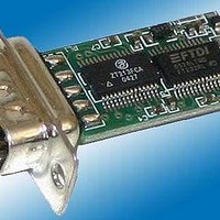
Interface Modules & Development Tools From FTDI UC232R CH iPi USB-RS232 Cable
Manufacturer
DLP Design Inc
Datasheet
1.UC232R.pdf
(10 pages)
Specifications of UC232R
Interface Type
RS-232, USB
Product
Interface Modules
For Use With/related Products
FT232RL
Lead Free Status / RoHS Status
Lead free / RoHS Compliant


6. Internal EEPROM Configuration
Following a power-on reset or a USB reset the FT232R will scan its internal EEPROM and read the USB configuration
descriptors stored there. The default values programmed into the internal EEPROM in the FT232RL used on the
UC232R are shown in Table 2.
Table 2 - Default Internal EEPROM Configuration
The internal EEPROM in the FT232R can be programmed over USB using the utility program MPROG. MPROG can
be downloaded from the
their own USB Vendor ID but who would like to use a unique Product ID in their design can apply to FTDI for a free
block of unique PIDs. Contact
UC232R “ChiPi” Minimum Component FT232RL USB to RS232 Converter Cable
Datasheet Version 0.90
Parameter
USB Vendor ID (VID)
USB Product ID (PID)
Serial Number Enabled?
Serial Number
Pull Down I/O Pins in USB Suspend
Manufacturer Name
Manufacturer ID
Product Description
Max Bus Power Current
Power Source
Device Type
USB Version
Remote Wake up
High Current I/Os
Load VCP Driver
CBUS0
CBUS1
CBUS2
CBUS3
CBUS4
Invert TXD
Invert RXD
Invert RTS#
Invert CTS#
Invert DTR#
Invert DSR#
Invert DCD#
Invert RI#
FTDI
FTDI support
website. Version 2.8a or later is required for the FT232R chip. Users who do not have
Chipi USB <-> Serial
Bus Powered
PWREN#
PWREN#
PWREN#
PWREN#
See Note
Disabled
Disabled
SLEEP#
Disabled
Disabled
Disabled
Disabled
Disabled
Disabled
Disabled
Disabled
FT232R
Enabled
Enabled
Value
for this service.
100mA
0403h
6001h
FTDI
0200
Yes
FT
Enabling this option will make the device pull down on the UART interface
A unique serial number is generated and programmed into the EEPROM
Returns USB 2.0 device descriptor to the host. Note: The device is be
a USB 2.0 Full Speed device (12Mb/s) as opposed to a USB 2.0 High
Default configuration of CBUS4 - Low during USB suspend. Used to
Taking RI# low will wake up the USB host controller from suspend.
Default configuration of CBUS0 - Power enable. Low after USB
Default configuration of CBUS1 - Power enable. Low after USB
Default configuration of CBUS2 - Power enable. Low after USB
Default configuration of CBUS3 - Power enable. Low after USB
Makes the device load the VCP driver interface for the device.
Enables the high drive level on the UART and CBUS I/O pins
power down the UC232R’s RS232 level converter IC.
lines when the power is shut off (PWREN# is high)
Signal on this pin becomes RXD# if enabled.
Signal on this pin becomes TXD# if enabled.
Signal on this pin becomes DCD if enabled.
Signal on this pin becomes CTS if enabled.
Signal on this pin becomes DTR if enabled.
Signal on this pin becomes DSR if enabled.
Signal on this pin becomes RTS if enabled.
Signal on this pin becomes RI if enabled.
enumeration, high during USB suspend.
enumeration, high during USB suspend.
enumeration, high during USB suspend.
enumeration, high during USB suspend.
during final test of the UC232R module.
© Future Technology Devices International Ltd. 2005
Speed device (480Mb/s).
FTDI default VID (hex)
FTDI default PID (hex)
Notes
Related parts for UC232R
Image
Part Number
Description
Manufacturer
Datasheet
Request
R

Part Number:
Description:
MODULE USB-TO-TTL PARL FIFO CONV
Manufacturer:
DLP Design Inc
Datasheet:

Part Number:
Description:
MODULE DATA-ACQUISITION 8-CH
Manufacturer:
DLP Design Inc
Datasheet:

Part Number:
Description:
MODULE DATA-ACQUISITION 20-CH
Manufacturer:
DLP Design Inc
Datasheet:

Part Number:
Description:
RFID READER/WRITER SNGL-CH OEM
Manufacturer:
DLP Design Inc
Datasheet:

Part Number:
Description:
Interface Modules & Development Tools DLP-245PL PACKAGED w/CCS Compiler
Manufacturer:
DLP Design Inc

Part Number:
Description:
Interface Modules & Development Tools DLP-245PB-G BOARD + CCS Compiler
Manufacturer:
DLP Design Inc
Datasheet:

Part Number:
Description:
Interface Modules & Development Tools DLP-TILT SENSOR ACCEL VIBRATION
Manufacturer:
DLP Design Inc

Part Number:
Description:
Zigbee / 802.15.4 Modules & Development Tools USE 626-DLP-RF2-Z
Manufacturer:
DLP Design Inc
Datasheet:

Part Number:
Description:
MODULE USB-MCU FT245RL W/16F877A
Manufacturer:
DLP Design Inc
Datasheet:

Part Number:
Description:
MODULE USB-TO-FPGA TRAINING TOOL
Manufacturer:
DLP Design Inc
Datasheet:

Part Number:
Description:
MODULE USB-MCU FT232R W/18F2410
Manufacturer:
DLP Design Inc
Datasheet:

Part Number:
Description:
MODULE USB-MCU FT245RL W/SX48
Manufacturer:
DLP Design Inc
Datasheet:

Part Number:
Description:
MODULE USB-MCU FT2232D W/16F877A
Manufacturer:
DLP Design Inc
Datasheet:

Part Number:
Description:
MODULE USB-TO-FPGA SPARTAN3
Manufacturer:
DLP Design Inc
Datasheet:

Part Number:
Description:
MOD USB-MCU FT245RL W/18LF8722
Manufacturer:
DLP Design Inc
Datasheet: