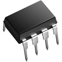
XRP7665EVB Exar Corporation, XRP7665EVB Datasheet - Page 9

XRP7665EVB
Manufacturer Part Number
XRP7665EVB
Description
Power Management Modules & Development Tools Eval Board for XRP7665 Series
Manufacturer
Exar Corporation
Type
PMIC Solutionsr
Datasheet
1.XRP7665EVB.pdf
(12 pages)
Specifications of XRP7665EVB
Maximum Operating Temperature
+ 85 C
Operating Supply Voltage
4.75 V to 18 V
Product
Power Management Development Tools
For Use With/related Products
XRP7665
Lead Free Status / RoHS Status
Lead free / RoHS Compliant
Where:
I
D is duty cycle (D=V
Calculate the C
Where:
ΔV
nominally set at 1% of V
O
An optional Schottky diode may be paralleled
between the GND pin and SW pin to improve
the regulator efficiency. Examples are shown
in Table 3.
EXTERNAL BOOTSTRAP DIODE
A
recommended for higher efficiency when the
input voltage is 5V or the output is 5V or 3.3V.
Circuit configuration is shown in figures 16 and
17. The external bootstrap diode is also
recommended where duty cycle (V
larger than 65%.
© 2011 Exar Corporation
OUT
PTIONAL
IN
Part Number
low-cost
is regulator’s maximum current (3A)
MBRS130
is the permissible input voltage ripple,
SK13
B130
Table 3. Optional Schottky diode
S
CHOTTKY DIODE
,
diode,
IN
Voltage/Current
capacitance from:
Rating
30V/1A
30V/1A
30V/1A
OUT
such
/V
IN
IN
)
as
1
International
Diodes, Inc.
Diodes, Inc.
Vendor
Rectifier
1N4148,
OUT
/V
IN
3
3
) is
A
A
is
1
1
9/12
8
8
V
V
LOOP COMPENSATION
XRP7665 utilizes current-mode control. This
allows
components to compensate the regulator. In
general only two components are needed: RC
and CC. Proper compensation of the regulator
(determining RC and CC) results in optimum
transient response. In terms of power supply
control theory, the goals of compensation are
to choose RC and CC such that the regulator
loop
between 15kHz and 34kHz. The corresponding
phase-margin should be between 45 degrees
and 65 degrees. An important characteristic of
current-mode buck regulator is its dominant
pole. The frequency of the dominant pole is
given by:
where R
The uncompensated regulator has a constant
gain up to its pole frequency, beyond which
S
S
V
y
y
IN
n
n
XRP7665
= 5V
c
c
gain
h
h
Fig. 16: Optional external bootstrap diode
Fig. 17: Optional external bootstrap diode
load
r
r
using
o
o
where output voltage is 5V or 3.3V
where input voltage is fixed at 5V
n
n
is the output load resistance.
o
has
o
u
u
SW
BS
s
s
a
2
S
S
IN
a
t
t
XRP7665
e
e
minimum
crossover
p
p
-
-
10nF
1
D
D
1N4148
o
o
w
w
SW
BS
n
n
X
X
frequency
C
C
of
R
R
o
o
P
n
P
n
Rev. 1.0.0
V
or 3.3V
v
external
v
OUT
7
7
1N4148
C
e
e
OUT
10nF
6
6
= 5V
r
r
6
t
6
t
e
e
5
5
fc
r
r


