CSTCE10M0G55-R0 Murata Electronics North America, CSTCE10M0G55-R0 Datasheet - Page 24
CSTCE10M0G55-R0
Manufacturer Part Number
CSTCE10M0G55-R0
Description
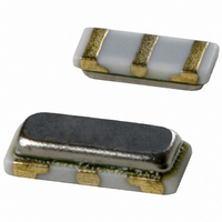
RESONATOR 10.0MHZ CERAMIC
Manufacturer
Murata Electronics North America
Series
CERALOCK®, CSTCEr
Type
Ceramicr
Specifications of CSTCE10M0G55-R0
Frequency
10MHz
Features
Built in Capacitor
Frequency Stability
±0.2%
Frequency Tolerance
±0.5%
Impedance
40 Ohm
Capacitance
33pF
Operating Temperature
-20°C ~ 80°C
Mounting Type
Surface Mount
Package / Case
3-SMD, Non-Standard
Size / Dimension
0.126" L x 0.051" W (3.20mm x 1.30mm)
Height
0.028" (0.70mm)
Lead Free Status / RoHS Status
Lead free / RoHS Compliant
Other names
490-1196-2
Available stocks
Company
Part Number
Manufacturer
Quantity
Price
Company:

Part Number:
CSTCE10M0G55-R0
Manufacturer:
MURATA
Quantity:
1 840


5
Note
• This PDF catalog is downloaded from the website of Murata Manufacturing co., ltd. Therefore, it’s specifications are subject to change or our products in it may be discontinued without advance notice. Please check with our
• This PDF catalog has only typical specifications because there is no space for detailed specifications. Therefore, please approve our product specifications or transact the approval sheet for product specifications before ordering.
sales representatives or product engineers before ordering.
This chapter describes the general characteristics of the basic
oscillation of Fig. 4-1 (page. 19). Contact Murata for detailed
characteristics of oscillation with specific kinds of ICs and LSIs.
Fig. 5-1 shows examples of actual measurements for stability
of the oscillation frequency.
The stability versus temperature change is ±0.1 to 0.5% within
a range of -20 to +80°C, although varies slightly depending on
the ceramic material.
Influence of load capacitance (C
frequency is relatively high, as seen in formula (4-1) (P.20).
It varies approximately ±0.05% for a capacitance deviation of
±10%. The stability versus supply voltage is normally within
±0.05% in the working voltage range, although it varies with
the characteristics of the IC.
22
Fig. 5-1 Examples of Actual Measurement for the Stability of Oscillation Frequency (IC: TC74HCU04(TOSHIBA), CERALOCK
1. Stability of Oscillation Frequency
5
+0.50
+0.25
+0.50
+0.25
+0.50
+0.25
-0.25
-0.50
-0.25
-0.50
-0.25
-0.50
0
0
0
0
0
Characteristics of CERALOCK
-40
C
L2
1
C
Temperature Characteristics
(C
L
L1
(C
= Constant) Characteristics
L1
1
= C
0
L2
L1
) Characteristics
10
, C
L2
) on the oscillation
40
C
C
L2
L
/C
(pF)
100
L1
10
80
V
V
C
V
DD
DD
DD
L1
= 6pF Const.
= +5V
= +5V
= +5V
Temperature (℃)
120
Max.
Min.
+0.50
+0.25
+0.50
+0.25
-0.25
-0.50
-0.25
-0.50
0
0
®
0
Oscillation Circuit
C
L1
Starting Voltage
Supply Voltage Characteristics
(C
2
L2
= Constant) Characteristics
1
4
®
: CSACW33M8X51–B0)
6
V
C
DD
L2
= 6pF Const.
= +5V
C
V
L1
DD
/C
L2
(V)
10
8
P17E.pdf
10.8.3
Related parts for CSTCE10M0G55-R0
Image
Part Number
Description
Manufacturer
Datasheet
Request
R

Part Number:
Description:
BUZZER PIEZO 25VP-P SMD
Manufacturer:
Murata Electronics North America

Part Number:
Description:
CAP 4-ARRAY 680PF 100V X7R 1206
Manufacturer:
Murata Electronics North America
Datasheet:
Part Number:
Description:
CAP 4-ARRAY 1000PF 100V X7R 1206
Manufacturer:
Murata Electronics North America
Datasheet:
Part Number:
Description:
CAP 4-ARRAY 1800PF 100V X7R 1206
Manufacturer:
Murata Electronics North America
Datasheet:
Part Number:
Description:
CAP 4-ARRAY 68000PF 16V X7R 1206
Manufacturer:
Murata Electronics North America
Datasheet:

Part Number:
Description:
CAP CER 1000PF 50V 10% X7R 0402
Manufacturer:
Murata Electronics North America
Datasheet:
Part Number:
Description:
CAP CER 10000PF 16V 10% X7R 0402
Manufacturer:
Murata Electronics North America
Datasheet:

Part Number:
Description:
CAP 5.5-25PF 2.5X3.2MM SMD
Manufacturer:
Murata Electronics North America
Datasheet:

Part Number:
Description:
CAP 4.5-20PF 2.5X3.2MM SMD
Manufacturer:
Murata Electronics North America
Datasheet:

Part Number:
Description:
CAP 5.0-20PF 3.2X4.5MM SMD RED
Manufacturer:
Murata Electronics North America
Datasheet:

Part Number:
Description:
CAP 2.0-6.0PF 3.2X4.5MM SMD BLU
Manufacturer:
Murata Electronics North America
Datasheet:

Part Number:
Description:
CAP 1.4-3.0PF 3.2X4.5MM SMD BRN
Manufacturer:
Murata Electronics North America
Datasheet:

Part Number:
Description:
CAP 3.0-10PF 3.2X4.5MM SMD WHT
Manufacturer:
Murata Electronics North America
Datasheet:

Part Number:
Description:
CAP 2.0-6.0PF 4X4.5MM TOPADJ BLU
Manufacturer:
Murata Electronics North America
Datasheet:

Part Number:
Description:
CAP 8.5-40PF 4X4.5MM TOPADJ YEL
Manufacturer:
Murata Electronics North America
Datasheet: