MB2S-E3/45 Vishay, MB2S-E3/45 Datasheet - Page 3
MB2S-E3/45
Manufacturer Part Number
MB2S-E3/45
Description
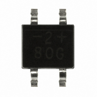
RECTIFIER BRIDGE 0.5A TO269AA
Manufacturer
Vishay
Datasheet
1.MB2S-E345.pdf
(4 pages)
Specifications of MB2S-E3/45
Voltage - Peak Reverse (max)
200V
Current - Dc Forward (if)
500mA
Diode Type
Single Phase
Speed
Standard Recovery >500ns, > 200mA (Io)
Mounting Type
Surface Mount
Package / Case
TO-269AA (MBS)
Product
Single Phase Bridge
Peak Reverse Voltage
200 V
Maximum Rms Reverse Voltage
140 V
Forward Continuous Current
0.5 A
Max Surge Current
35 A
Forward Voltage Drop
1 V
Maximum Reverse Leakage Current
5 uA
Maximum Operating Temperature
+ 150 C
Length
4.95 mm
Width
4.1 mm
Height
2.7 mm
Mounting Style
SMD/SMT
Minimum Operating Temperature
- 55 C
No. Of Phases
Single
Repetitive Reverse Voltage Vrrm Max
200V
Forward Current If(av)
500mA
Forward Voltage Vf Max
1V
Diode Mounting Type
SMD
Operating Temperature Range
-55°C To +150°C
Lead Free Status / RoHS Status
Lead free / RoHS Compliant
Reverse Recovery Time (trr)
-
Lead Free Status / Rohs Status
Lead free / RoHS Compliant
Other names
MB2S-E3/1
MB2S-E3/1GI
MB2S-E3/1GI
MB2S-E3/45GI
MB2S-E3/1GI
MB2S-E3/1GI
MB2S-E3/45GI
Available stocks
Company
Part Number
Manufacturer
Quantity
Price


PACKAGE OUTLINE DIMENSIONS in inches (millimeters)
Document Number: 88661
Revision: 01-Feb-08
Figure 4. Typical Reverse Leakage Characteristics Per Diode
Figure 3. Typical Forward Voltage Characteristics Per Diode
0.01
0.01
100
0.1
0.1
10
10
1
1
0.3
0
Percent of Rated Peak Reverse Voltage (%)
0.5
Instantaneous Forward Voltage (V)
20
0.114 (2.90)
0.094 (2.40)
T
J
0.7
= 150 °C
T
T
0.106 (2.70)
0.090 (2.30)
0.144 (3.65)
J
J
0.161 (4.10)
40
= 125 °C
= 25 °C
PDD-Americas@vishay.com, PDD-Asia@vishay.com, PDD-Europe@vishay.com
For technical questions within your region, please contact one of the following:
0.9
0.029 (0.74)
0.017 (0.43)
Pulse Width = 300 µs
1 % Duty Cycle
60
T
J
1.1
= 25 °C
0.095 (2.41)
0.195 (4.95)
0.105 (2.67)
0.179 (4.55)
80
1.3
TO-269AA (MBS)
0.0075 (0.19)
0.0065 (0.16)
0.038 (0.96)
0.019 (0.48)
0.272 (6.90)
0.252 (6.40)
100
1.5
0 to 8°
0.058 (1.47)
0.054 (1.37)
0.195 (4.95)
0.008 (0.20)
0.004 (0.10)
0.114 (2.90)
0.110 (2.80)
0.205 (5.21)
0.016 (0.41)
0.006 (0.15)
0.018 (0.46)
0.014 (0.36)
0.049 (1.24)
0.039 (0.99)
0.062 (1.57)
0.058 (1.47)
30
25
20
15
10
5
0
Figure 5. Typical Junction Capacitance Per Diode
0.1
(0.58 MIN.)
Vishay General Semiconductor
0.023 MIN.
(0.76 MIN.)
0.030 MIN.
Mounting Pad Layout
MB2S, MB4S & MB6S
1
Reverse Voltage (V)
0.105 (2.67)
0.095 (2.41)
10
0.272 MAX.
(6.91 MAX.)
T
f = 1.0 MHz
V
J
sig
= 25 °C
100
= 50 mVp-p
www.vishay.com
1000
3
Related parts for MB2S-E3/45
Image
Part Number
Description
Manufacturer
Datasheet
Request
R

Part Number:
Description:
DIODE BRIDGE 0.5A TO-269AA
Manufacturer:
Vishay
Datasheet:

Part Number:
Description:
IC RECT BRIDGE 0.5A 200V 4SOIC
Manufacturer:
Fairchild Semiconductor
Datasheet:

Part Number:
Description:
RECTIFIER BRIDGE SMD TO-269AA
Manufacturer:
Vishay
Datasheet:

Part Number:
Description:
0.5A, 200V Bridge Rectifier, MBS-1 / 13" REEL
Manufacturer:
Micro Commercial Components (MCC)
Datasheet:


Part Number:
Description:
Bridge Rectifiers 0.5 Amp 400 Volt
Manufacturer:
Vishay
Datasheet:

Part Number:
Description:
Manufacturer:
Sensitron Semiconductors
Datasheet:
Part Number:
Description:
357-036-542-201 CARDEDGE 36POS DL .156 BLK LOPRO
Manufacturer:
Vishay
Datasheet:
Part Number:
Description:
357-036-542-201 CARDEDGE 36POS DL .156 BLK LOPRO
Manufacturer:
Vishay
Datasheet:
Part Number:
Description:
357-036-542-201 CARDEDGE 36POS DL .156 BLK LOPRO
Manufacturer:
Vishay
Datasheet:
Part Number:
Description:
357-036-542-201 CARDEDGE 36POS DL .156 BLK LOPRO
Manufacturer:
Vishay
Datasheet:
Part Number:
Description:
357-036-542-201 CARDEDGE 36POS DL .156 BLK LOPRO
Manufacturer:
Vishay
Datasheet:
Part Number:
Description:
357-036-542-201 CARDEDGE 36POS DL .156 BLK LOPRO
Manufacturer:
Vishay
Datasheet:
Part Number:
Description:
357-036-542-201 CARDEDGE 36POS DL .156 BLK LOPRO
Manufacturer:
Vishay
Datasheet: