2W06G-E4/51 Vishay, 2W06G-E4/51 Datasheet - Page 3
2W06G-E4/51
Manufacturer Part Number
2W06G-E4/51
Description
RECTIFIER BRIDGE 2A 600V WOG
Manufacturer
Vishay
Datasheet
1.2W005G-E451.pdf
(4 pages)
Specifications of 2W06G-E4/51
Voltage - Peak Reverse (max)
600V
Current - Dc Forward (if)
2A
Diode Type
Single Phase
Speed
Standard Recovery >500ns, > 200mA (Io)
Mounting Type
Through Hole
Package / Case
WOG
Product
Single Phase Bridge
Peak Reverse Voltage
600 V
Maximum Rms Reverse Voltage
420 V
Max Surge Current
60 A
Forward Voltage Drop
1.1 V
Maximum Reverse Leakage Current
5 uA
Maximum Operating Temperature
+ 150 C
Length
9.86 mm
Width
8.84 mm
Height
5.6 mm
Mounting Style
SMD/SMT
Minimum Operating Temperature
- 55 C
No. Of Phases
1
Repetitive Reverse Voltage Vrrm Max
600V
Forward Current If(av)
2A
Forward Voltage Vf Max
1.1V
Diode Mounting Type
Through Hole
Operating Temperature Range
-55°C To +150°C
Rohs Compliant
Yes
Lead Free Status / RoHS Status
Lead free / RoHS Compliant
Reverse Recovery Time (trr)
-
Lead Free Status / Rohs Status
Lead free / RoHS Compliant
Other names
2W06G
2W06G-E4/1
2W06G-E4/1
2W06G-E4/1
2W06G-E4/1
Available stocks
Company
Part Number
Manufacturer
Quantity
Price
Company:

Part Number:
2W06G-E4/51
Manufacturer:
SAMSUNG
Quantity:
4 600


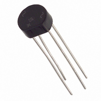
PACKAGE OUTLINE DIMENSIONS in inches (millimeters)
Document Number: 88528
Revision: 15-Apr-08
Figure 4. Typical Reverse Leakage Characteristics Per Diode
0.01
0.01
100
100
0.1
0.1
10
Figure 3. Typical Forward Characteristics Per Diode
10
1
1
0.4
0
T
Pulse Width = 300 µs
1 % Duty Cycle
Percent of Rated Peak Reverse Voltage (%)
J
= 25 °C
0.6
Instantaneous Forward Voltage (V)
20
0.8
40
PDD-Americas@vishay.com, PDD-Asia@vishay.com, PDD-Europe@vishay.com
For technical questions within your region, please contact one of the following:
1.0
T
T
T
J
J
J
60
= 100 °C
= 25 °C
= 125 °C
1.2
80
1.4
0.220 (5.6)
0.160 (4.1)
0.308 (7.82)
0.348 (8.84)
0.032 (0.81)
0.028 (0.71)
100
1.6
Case Style WOG
0.388 (9.86)
0.348 (8.84)
0.220 (5.6)
0.180 (4.6)
1.0 (25.4) MIN.
100
100
10
10
0.1
1
0.220 (5.6)
0.180 (4.6)
Figure 5. Typical Junction Capacitance Per Diode
1
0.060 (1.52)
0.01
0.020 (0.51)
0.1
Figure 6. Typical Transient Thermal Impedance
Vishay General Semiconductor
0.1
2W005G thru 2W10G
Reverse Voltage (V)
t - Heating Time (s)
1
1
10
T
f = 1.0 MHz
V
J
sig
10
= 25 °C
= 50 mVp-p
www.vishay.com
100
100
3
Related parts for 2W06G-E4/51
Image
Part Number
Description
Manufacturer
Datasheet
Request
R

Part Number:
Description:
BRIDGE RECTIFIER, 1PH, 2A, 600V THD
Manufacturer:
Vishay
Datasheet:


Part Number:
Description:
357-036-542-201 CARDEDGE 36POS DL .156 BLK LOPRO
Manufacturer:
Vishay
Datasheet:
Part Number:
Description:
357-036-542-201 CARDEDGE 36POS DL .156 BLK LOPRO
Manufacturer:
Vishay
Datasheet:
Part Number:
Description:
357-036-542-201 CARDEDGE 36POS DL .156 BLK LOPRO
Manufacturer:
Vishay
Datasheet:
Part Number:
Description:
357-036-542-201 CARDEDGE 36POS DL .156 BLK LOPRO
Manufacturer:
Vishay
Datasheet:
Part Number:
Description:
357-036-542-201 CARDEDGE 36POS DL .156 BLK LOPRO
Manufacturer:
Vishay
Datasheet:
Part Number:
Description:
357-036-542-201 CARDEDGE 36POS DL .156 BLK LOPRO
Manufacturer:
Vishay
Datasheet:
Part Number:
Description:
357-036-542-201 CARDEDGE 36POS DL .156 BLK LOPRO
Manufacturer:
Vishay
Datasheet:
Part Number:
Description:
357-036-542-201 CARDEDGE 36POS DL .156 BLK LOPRO
Manufacturer:
Vishay
Datasheet:
Part Number:
Description:
357-036-542-201 CARDEDGE 36POS DL .156 BLK LOPRO
Manufacturer:
Vishay
Datasheet:
Part Number:
Description:
357-036-542-201 CARDEDGE 36POS DL .156 BLK LOPRO
Manufacturer:
Vishay
Datasheet:
Part Number:
Description:
357-036-542-201 CARDEDGE 36POS DL .156 BLK LOPRO
Manufacturer:
Vishay
Datasheet:
Part Number:
Description:
357-036-542-201 CARDEDGE 36POS DL .156 BLK LOPRO
Manufacturer:
Vishay
Datasheet: