GBU6J-E3/51 Vishay, GBU6J-E3/51 Datasheet

DIODE GPP 6A 600V GPP INLINE GBU

GBU6J-E3/51

Manufacturer Part Number
GBU6J-E3/51
Description
DIODE GPP 6A 600V GPP INLINE GBU
Manufacturer
Vishay
Datasheet

Specifications of GBU6J-E3/51

Voltage - Peak Reverse (max)
600V
Current - Dc Forward (if)
3.8A
Diode Type
Single Phase
Speed
Standard Recovery >500ns, > 200mA (Io)
Mounting Type
Through Hole
Package / Case
4-SIP (GBU)
Product
Single Phase Bridge
Peak Reverse Voltage
600 V
Maximum Rms Reverse Voltage
420 V
Max Surge Current
175 A
Forward Voltage Drop
1 V
Maximum Reverse Leakage Current
5 uA
Maximum Operating Temperature
+ 150 C
Length
22.3 mm
Width
3.56 mm
Height
18.8 mm
Mounting Style
Through Hole
Minimum Operating Temperature
- 55 C
No. Of Phases
Single
Repetitive Reverse Voltage Vrrm Max
600V
Forward Current If(av)
6A
Forward Voltage Vf Max
1V
Diode Mounting Type
Through Hole
Operating Temperature Range
-55°C To +150°C
Lead Free Status / RoHS Status
Lead free / RoHS Compliant
Reverse Recovery Time (trr)
-
Lead Free Status / RoHS Status
Lead free / RoHS Compliant, Lead free / RoHS Compliant
Other names
GBU6J-E3/45

Available stocks

Company
Part Number
Manufacturer
Quantity
Price
Part Number:
GBU6J-E3/51
Manufacturer:
VISHAY/威世
Quantity:
20 000
Notes:
(1) Unit case mounted on aluminum plate heatsink
(2) Units mounted on P.C.B. with 0.5 x 0.5" (12 x 12 mm) copper pads and 0.375" (9.5 mm) lead length
Document Number: 88615
Revision: 15-Dec-08
PRIMARY CHARACTERISTICS
MAXIMUM RATINGS (T
PARAMETER
Maximum repetitive peak reverse voltage
Maximum RMS voltage
Maximum DC blocking voltage
Maximum average forward
rectified output current at (Fig. 1)
Peak forward surge current single sine-wave
superimposed on rated load
Rating for fusing (t < 8.3 ms)
Operating junction and storage
temperature range
T
V
I
J
I
F(AV)
FSM
RRM
V
I
max.
R
F
Glass Passivated Single-Phase Bridge Rectifier
Case Style GBU
PDD-Americas@vishay.com, PDD-Asia@vishay.com, PDD-Europe@vishay.com
For technical questions within your region, please contact one of the following:
T
T
A
C
A
= 25 °C unless otherwise noted)
= 40 °C
= 90 °C
50 V to 1000 V
150 °C
(1)
(2)
175 A
6.0 A
1.0 V
5 µA
SYMBOL
T
J
V
V
I
I
V
, T
F(AV)
FSM
RRM
RMS
I
DC
2
t
STG
GBU6A
50
35
50
GBU6B
FEATURES
TYPICAL APPLICATIONS
General purpose use in ac-to-dc bridge full wave
rectification for monitor, TV, printer, switching mode
power supply, adapter, audio equipment, and home
appliances applications.
MECHANICAL DATA
Case: GBU
Epoxy meets UL 94 V-0 flammability rating
Terminals: Matte tin plated leads, solderable per
J-STD-002 and JESD22-B102
E3 suffix for consumer grade, meets JESD 201 class
1A whisker test
Polarity: As marked on body
Mounting Torque: 10 cm-kg (8.8 inches-lbs) max.
Recommended Torque: 5.7 cm-kg (5 inches-lbs)
• UL recognition file number E54214
• Ideal for printed circuit boards
• High surge current capability
• High case dielectric strength of 1500 V
• Solder dip 260 °C, 40 s
• Component in accordance to RoHS 2002/95/EC
100
100
70
and WEEE 2002/96/EC
GBU6D
200
140
200
Vishay General Semiconductor
- 55 to + 150
GBU6G
400
280
400
175
127
6.0
3.8
GBU6A thru GBU6M
GBU6J
600
420
600
GBU6K
800
560
800
GBU6M UNIT
www.vishay.com
RMS
1000
1000
700
A
°C
V
V
V
A
A
2
s
1

Related parts for GBU6J-E3/51

GBU6J-E3/51 Summary of contents

Page 1

... RMS V 50 100 DC (1) I (2) F(AV) I FSM STG GBU6A thru GBU6M Vishay General Semiconductor RMS GBU6G GBU6J GBU6K GBU6M UNIT 200 400 600 800 1000 140 280 420 560 700 200 400 600 800 1000 6.0 3.8 175 127 - 150 www.vishay.com ...

Page 2

... Units mounted in free air, no heatsink on P.C.B., 0.5 x 0.5" ( mm) copper pads, 0.375" (9.5 mm) lead length (3) Recommended mounting position is to bolt down on heatsink with silicone thermal compound for maximum heat transfer with #6 screws ORDERING INFORMATION PREFERRED P/N UNIT WEIGHT (g) GBU6J-E3/45 3.857 GBU6J-E3/51 3.857 RATINGS AND CHARACTERISTICS CURVES ( °C unless otherwise noted) A 6.0 ...

Page 3

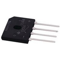
... Polarity shown on front side of case, positive lead by beveled corner Document Number: 88615 For technical questions within your region, please contact one of the following: Revision: 15-Dec-08 PDD-Americas@vishay.com, PDD-Asia@vishay.com, PDD-Europe@vishay.com 1000 100 10 1.4 1.6 Figure 5. Typical Junction Capacitance Per Diode ...

Page 4

... Vishay product could result in personal injury or death. Customers using or selling Vishay products not expressly indicated for use in such applications their own risk and agree to fully indemnify and hold Vishay and its distributors harmless from and against any and all claims, liabilities, expenses and damages arising or resulting in connection with such use or sale, including attorneys fees, even if such claim alleges that Vishay or its distributor was negligent regarding the design or manufacture of the part ...

Related keywords