Standard Resistance Range .................................................................................................................................................100 ohms to 1 megohm
Total Resistance Tolerance ............................................................................................................................................................... (A Taper) ±10 %
Independent Linearity ........................................................................................................................................................................................ ±5 %
Absolute Minimum Resistance ...................................................................................................................................................... 2 ohms maximum
Effective Electrical Angle .......................................................................................................................................................................... 260 ° ±10 °
Contact Resistance Variation ........................................................................................................................ ±3 % or 6 ohms (whichever is greater)
Dielectric Withstanding Voltage (MIL-STD-202, Method 301)
Insulation Resistance (500 VDC) ...................................................................................................................................... 1,000 megohms minimum
Power Rating (Voltage Limited by Power Dissipation or 350 VAC, Whichever is Less)
Theoretical Resolution ................................................................................................................................................................... Essentially infi nite
Operating Temperature Range ...................................................................................................................................................... -40 °C to +125 °C
Storage Temperature Range ......................................................................................................................................................... -65 °C to +125 °C
Temperature Coeffi cient Over Storage Temperature Range ................................................................................................................ ±150 ppm/°C
Vibration ............................................................................................................................................................................................................ 20 G
Shock ................................................................................................................................................................................................................. 50 G
Load Life ..................................................................................................................................................................................................1,000 hours
Rotational Life (C & N Bushing) No Load .............................................................................................................................................50,000 cycles
Moisture Resistance (MIL-STD-202, Method 106, Condition B)
Salt Spray ...................................................................................................................................................MIL-STD-202, Method 101, Condition A
IP Rating .............................................................................................................................................................................................................IP 40
Stop Strength ............................................................................................................................................................... 33 N-cm (3 lb.-in.) maximum
Mechanical Angle ....................................................................................................................................................................................... 295 ° ±3 °
Torque
Weight (Single Section)............................................................................................................................................................... 25 grams maximum
Terminals ................................................................................................................................................................... Printed circuit pins or J-Hooks
Marking .................................................................Manufacturer’s trademark, wiring diagram, date code, resistance, manufacturer’s part number
Ganging ............................................................................................................................................................................................ 1 cup maximum
Hardware ........................... One lockwasher and one mounting nut is shipped with each potentiometer, except where noted in the part number.
1 AT ROOM AMBIENT: +25 °C NOMINAL AND 50 % RELATIVE HUMIDITY NOMINAL, EXCEPT AS NOTED.
Initial Electrical Characteristics
Environmental Characteristics
Mechanical Characteristics
Sea Level ................................................................................................................................................................................ 750 VAC minimum
70,000 Feet ............................................................................................................................................................................. 350 VAC minimum
+70 °C......................................................................................................................................................................................................... 1 watt
+125 °C....................................................................................................................................................................................................... 0 watt
Total Resistance Shift ................................................................................................................................................................. ±2 % maximum
Voltage Ratio Shift ...................................................................................................................................................................... ±6 % maximum
Total Resistance Shift ................................................................................................................................................................. ±3 % maximum
Total Resistance Shift ................................................................................................................................................................. ±5 % maximum
Contact Resistance Variation ...................................................................................................................................................................... ±3 %
Total Resistance Shift ................................................................................................................................................................. ±2 % maximum
Insulation Resistance (500 VDC) ................................................................................................................................... 100 megohms minimum
Starting and Running .......................................................................................................................................... 3.53 N-cm (5 oz.-in.) maximum
Mounting (Torque on Bushing)................................................................................................................... 1.7-2.0 N-m (15-18 lb.-in.) maximum
Shaft Locking Torque with Locking Bushings ................................................................................................................. 14.12 N-cm (20 oz.-in.)
Soldering Condition .................................................... Recommended hand soldering using Sn85/Ag5 no clean solder, 0.025 ” wire diameter
1
1
1
Maximum temperature 399 °C (750 °F) for 3 seconds. No wash process to be used with no clean fl ux.
Part can be wave soldered at 260 °C (500 °F) for 5 seconds, no wash process with no clean fl ux.
Features
■
■
■
■
■
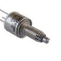
3862 - 1/2 ” Diameter Single-Turn Panel Control
Small diameter
Wide resistance range
Good resolution
Linear tapers
Cermet element
Customers should verify actual device performance in their specifi c applications.
*RoHS Directive 2002/95/EC Jan 27, 2003 including Annex.
Specifi cations are subject to change without notice.
(H Taper) ±5%