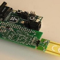
MC33696MOD434EV Freescale Semiconductor, MC33696MOD434EV Datasheet - Page 42

MC33696MOD434EV
Manufacturer Part Number
MC33696MOD434EV
Description
MCU, MPU & DSP Development Tools MC33696 (ECHO) RF C EVAL
Manufacturer
Freescale Semiconductor
Specifications of MC33696MOD434EV
Processor To Be Evaluated
MC9S08RG60
Interface Type
RS-232
Lead Free Status / RoHS Status
Lead free / RoHS Compliant
Controller
output data are complemented also. When an EOM occurs before the current byte is fully shifted out,
dummy bits are inserted until the number of shifted bits is a multiple of 8.
For all states: At any time, a low level applied to STROBE puts the circuit into state 20, and a low level
applied to CONFB forces the state machine to state 1.
18.4 Standby/LVD Mode
Standby/LVD mode allows minimum current consumption to be achieved. Depending upon the value of
the LVDE bit, the circuit is in standby mode (state 60) or LVD mode (state 5 and 20).
LVDE = 0: The transceiver is in standby; consumption is reduced to leakage current (current state after
POR).
LVDE = 1: The LVD function is enabled; consumption is in the range of tens of microamperes.
The only way to exit this mode is to go back to configuration mode by applying a low level to CONFB.
18.5 Transition Time
Table 24
the logic conditions for that transition are met.
NOTES:
1
2
42
Standby to SPI running, state 60 -> 1
Standby to receiver running, states 5 -> 5b, 20 -> 21
Off to receiver running, states 0 -> 0b, 10 -> 11
Configuration to receiver running,
states 1 -> (0b, 5b, 11, 21)
Configuration to transmitter mode, state 1 -> 30
Receiver running to configuration mode,
state (0b, 5b, 11, 12, 13, 21, 22, 23) -> 1,
Transmitter mode to configuration mode,
state 30 -> 1
Receiver running to standby mode,
state 5b -> 5, (21, 22, 23) -> 20
Receiver running to off mode,
state 0b -> 0, (11, 12, 13) -> 10
See
Depending on the PLL status before entering configuration mode. For example, the transition time from standby to receiver
running (FSK modulation, 19.2 kBd, AFFC = 0, data manager enabled) is: 0.6 ms + 50 µs + (3 + 1)/19.2k = 970 µs.
Section 12.2, “Preamble, Identifier, Header, and
details the different times that must be considered for a given transition in the state machine, once
State x -> y
Transition
Table 24. Transition Time Definition
MC33696 Data Sheet, Rev. 9
Parameter 5.10
Message.”
Startup Time,
Oscillator
Crystal
√
√
√
parameter 5.1 or lock
parameter 5.1 or lock
time parameter 5.9
time parameter 5.9
Lock time parameter
Lock time parameter
0 or lock time
0 or lock time
PLL Timing
5.9
5.9
2
2
Preamble
Receiver
Time
Freescale Semiconductor
√
√
√
1
On-to-Off Time,
Parameter 1.12
Receiver
√
√


