EA-QSB-003 Embedded Artists, EA-QSB-003 Datasheet - Page 20
EA-QSB-003
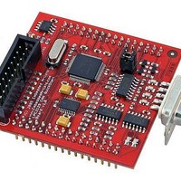
Manufacturer Part Number
EA-QSB-003
Description
MCU, MPU & DSP Development Tools LPC2129 CAN QUICKSTART BRD
Manufacturer
Embedded Artists
Specifications of EA-QSB-003
Processor To Be Evaluated
LPC2129
Data Bus Width
16 bit, 32 bit
Interface Type
RS-232, CAN, I2C, SPI, UART
Core
ARM7TDMI-S
Dimensions
55 mm x 58 mm
Maximum Operating Temperature
+ 85 C
Operating Supply Voltage
5 V
Lead Free Status / RoHS Status
Lead free / RoHS Compliant


NXP Semiconductors
Product data sheet
LPC2109_2119_2129_6
6.17.1 Features
6.18.1 Crystal oscillator
6.18 System control
Three match registers can be used to provide a PWM output with both edges controlled.
Again, the MR0 match register controls the PWM cycle rate. The other match registers
control the two PWM edge positions. Additional double edge controlled PWM outputs
require only two match registers each, since the repetition rate is the same for all PWM
outputs.
With double edge controlled PWM outputs, specific match registers control the rising and
falling edge of the output. This allows both positive going PWM pulses (when the rising
edge occurs prior to the falling edge), and negative going PWM pulses (when the falling
edge occurs prior to the rising edge).
The oscillator supports crystals in the range of 1 MHz to 30 MHz. The oscillator output
frequency is called f
purposes of rate equations, etc.. f
running and connected. Refer to
•
•
•
•
•
•
•
•
Seven match registers allow up to six single edge controlled or three double edge
controlled PWM outputs, or a mix of both types.
The match registers also allow:
– Continuous operation with optional interrupt generation on match.
– Stop timer on match with optional interrupt generation.
– Reset timer on match with optional interrupt generation.
Supports single edge controlled and/or double edge controlled PWM outputs. Single
edge controlled PWM outputs all go HIGH at the beginning of each cycle unless the
output is a constant LOW. Double edge controlled PWM outputs can have either edge
occur at any position within a cycle. This allows for both positive going and negative
going pulses.
Pulse period and width can be any number of timer counts. This allows complete
flexibility in the trade-off between resolution and repetition rate. All PWM outputs will
occur at the same repetition rate.
Double edge controlled PWM outputs can be programmed to be either positive going
or negative going pulses.
Match register updates are synchronized with pulse outputs to prevent generation of
erroneous pulses. Software must ‘release’ new match values before they can become
effective.
May be used as a standard timer if the PWM mode is not enabled.
A 32-bit Timer/Counter with a programmable 32-bit Prescaler.
osc
Rev. 06 — 10 December 2007
and the ARM processor clock frequency is referred to as CCLK for
Section 6.18.2 “PLL”
osc
and CCLK are the same value unless the PLL is
LPC2109/2119/2129
Single-chip 16/32-bit microcontrollers
for additional information.
© NXP B.V. 2007. All rights reserved.
20 of 44
Related parts for EA-QSB-003
Image
Part Number
Description
Manufacturer
Datasheet
Request
R

Part Number:
Description:
MCU, MPU & DSP Development Tools QUICKSTART PROTOTYPE BRD W/ LPC2129 CAN
Manufacturer:
Embedded Artists
Datasheet:

Part Number:
Description:
MCU, MPU & DSP Development Tools QUICKSTART PROTOTYPE BRD
Manufacturer:
Embedded Artists
Datasheet:

Part Number:
Description:
MCU, MPU & DSP Development Tools LPC2148 USB QUICKSTART BRD
Manufacturer:
Embedded Artists
Datasheet:

Part Number:
Description:
MCU, MPU & DSP Development Tools QUICKSTART PROTOTYPE BRD W/ LPC2106 RS232
Manufacturer:
Embedded Artists
Datasheet:
Part Number:
Description:
MCU, MPU & DSP Development Tools QUICKSTART PROTOTYPE BRD W/ LPC2148
Manufacturer:
Embedded Artists
Datasheet:
Part Number:
Description:
MCU, MPU & DSP Development Tools LPC2106 RS232 QUICKSTART BRD
Manufacturer:
Embedded Artists
Datasheet:

Part Number:
Description:
BOARD QUICK START LPC1343
Manufacturer:
Embedded Artists
Datasheet:

Part Number:
Description:
Development Boards & Kits - ARM QUICK START BOARD LPC11U35
Manufacturer:
Embedded Artists
Datasheet:
Part Number:
Description:
KIT LPC3141 SODIMM 66X48 200POS
Manufacturer:
Embedded Artists
Datasheet:
Part Number:
Description:
KIT LPC3152 SODIMM 66X48 200POS
Manufacturer:
Embedded Artists
Datasheet:
Part Number:
Description:
BOARD OEM W/LPC2478 MCU
Manufacturer:
Embedded Artists
Datasheet:
Part Number:
Description:
KIT LPC3250 259 WITH QVGA
Manufacturer:
Embedded Artists
Datasheet: