SUPERPRO-3000U Xeltek, SUPERPRO-3000U Datasheet
SUPERPRO-3000U
Specifications of SUPERPRO-3000U


Related parts for SUPERPRO-3000U


SUPERPRO-3000U Summary of contents
Page 1
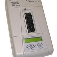
... General Description 1.1 INTRODUCTION 1.1.1 What is Superpro? The SUPERPRO is a series of cost-effective, reliable, and high-speed universal programmers. They are designed to communicate through a USB or parallel port (model dependent) and to operate with most IBM-compatible desktop computers and notebook computers. Their menu-driven software interface makes them easy to operate ...
Page 2
... Manual Organization This booklet consists of five main chapters: Chapter 1: Provides an introduction to the SUPERPRO series, including system requirements. Chapter 2: Provides system set up information, such as set-up of the hardware and software as well as solutions for communication error if encountered. Chapter 3: Provides pre-programming guidance and device selection, loading and reading data. ...
Page 3
... System Setup Parallel-based programmer’s software installation is straightforward and self-explanatory. If it’s your first time to use the USB-based programmer of XELTEK, this chapter will help you to properly install the software and connect the hardware. USB devices are PnP devices. At first installation, Windows will start with “ ...
Page 4
... SETUP.EXE in the root path. Caution: Each model has its own software, please do not mismatch. 2.1.2 Download software from the Internet You can download the specific software for a certain model at Xeltek website usually a self-extracting file. You only need to run this file to setup the software. ...
Page 5
Setup Process The setup procedure goes step by step, you can change the default settings as you needed during setup process. First, setup wizard, please read the text carefully. Click “next” button Second, select destination fold ...
Page 6
Third, as following ...
Page 7
Click “Install” button Fourth, copying files please wait ...
Page 8
Fifth, click “Finish” button to finish the setup. ...
Page 9
Hardware Setup Connect the programmer module to the computer’s USB port or parallel port. Turn on the programmer power switch. The driver installation is very simple, only need to wait until new hardware wizard finish installation during the installation, ...
Page 10
If communication error occurred, Please check the steps below: ·Connect the programmer to PC, and turn on the power switch ·Correct installation. If the programmer is connected before the software installation, PC will detect new hardware. The window appears as ...
Page 11
Please click “Cancel” to avoid troubles. 2.2 How to resolve the communication error If incorrect installation makes the PC fail to communicate with the programmer, please follow the steps below. Windows 98/ME: reinstall the software, turn off the power switch ...
Page 12
Caution: Under Windows XP, there are some options during the driver installation, please don’t change the default settings. 3 Quick Guide This chapter helps users understand the whole process of IC program. The content includes: ·The UI of the software ...
Page 13
Description of Interface The interface is as following: 1. Main Menu 2. Toolbar 4. Edit Buffer 5. Device Messages 7. Operation Toolbar 8. Device Function 9. Operation Message 10. Process Bar 3. Select Device 6. File Message ...
Page 14
... Hardware Preparation First, make sure the programmer is properly connected with the PC, and communication established successfully with the PC. (Some SMD devices need adapters, please contact Xeltek or its dealers for your adapter needs.) Second, insert the chip correctly. (Instruction for SMD and non-standard insertion will appear on the screen when the selection of the device is made instruction appears, chip insertion orientation should follow the guideline of the chips marking near the pin-driver socket ...
Page 15
... Program the Data in Memory Buffer into a Chip If the chip package is not DIP encapsulation, user may need to buy the adapter according to the info in the Adapter box. (Contact Xeltek for selection and purchase the adapters.) Insert the chip properly into the socket; following by these steps: · ...
Page 16
The programming cannot be implemented unless passing the Verification ·If the chip to program is not blank, you should add Erase before the Blank Check. ·If encryption is required, add Security or Protect after Verify ...
Page 17
To select a data file to be loaded, the path and the file name should be entered into the name field. If the full path or the exact name of the file is unknown, then a partial path may be ...
Page 18
If the start address is unknown, choose this option (at Left, Lower screen corner) – Show Offset Address after Loading. 2. Data are filled into buffer from this address 3. Data loaded into data buffer from this address 4. ...
Page 19
For E/EPROM, BPROM or MCU device types, Save File window will popup. Select the folder and filename to be saved under. Next, File Type dialog box will popup for selecting file type to be saved under. For PLD devices, the ...
Page 20
In Locate Buffer dialog box, enter the address you wish to see displayed and press OK. The cursor will blink at address. ·Fill The function will bring up the Fill Data Into Buffer dialogue box. It consists of the ...
Page 21
Swap MSB and LSB byte order for the specified word width in the address range. For example, assuming data buffer addresses 0-10(HEX) is – ...
Page 22
Note the three important options in the Buffer Edit dialogue box: ·Buffer clear at IC change: clear the buffer after device being selected ·Buffer clear on data load: clear the buffer before load file data ·Buffer save when exit: save ...
Page 23
Fuse data buffer 00000768 10011010101010101010101010101010 00000800 01101010101010101010101010101010 00000832 10100110101010101010101010101010 00000864 10101010011010101010101010101010 00000896 10101010101001101010101010101010 00000928 10101010101010100110101010101010 00000960 10101010101010101010011010101010 00000992 10101010101010101010101001101010 4.1.2.3 Encryption Table The Load Encryption Table, with its two sub-menus, manages an encryption array. The two sub-menus will appear only ...
Page 24
Z: High impedance state X: Don’t care state N: Vcc and Ground (output pins are not tested) H: Output logic High (VOH) L: Output logic Low (VOL) C: Clock pin 1: Input logic High (VIH) 0: Input logic Low (VIL) ...
Page 25
The function brings up Select Device dialogue box. It consists of Manufacturer list viewer, Device Name list viewer, Device Type button and OK, Cancel button, and Search Edit box. How to select a device? ·Select the device type through the ...
Page 26
Using Search Edit box reduces the number of devices listed, a convenient function for users; but please be sure only correct character string is entered, or users would not be able to find the specific devices. Therefore please double check ...
Page 27
Adapter Information The programmer is equipped with a standard DIP socket. For some device types, users need to use appropriate adapters. The Adapter Information dialogue box including: ·Adapter type such as SA244 ·PEP may be necessary to program devices ...
Page 28
Socket adapters are available for PLCC, QFP, SOIC etc. Insert the chip according to the instructions in the Adapter Information box. The insertion follows the position of pin necessary to identify the pin 1 of the ...
Page 29
DIP devices. Note: usually the front side of the chip is placed upwards; but for PLCC 20-pin chip, it needs to be placed with the front side downwards. This method is called ...
Page 30
... PEP3000 (100 pin expansion module) may be required. The module can only be used with Superpro 3000U Programmer. Insert the adapter into the PEP3000 module. ...
Page 31
·For economic programmer, perhaps special insertion needed. ...
Page 32
Options This function helps users to program in a specific mode to meet the targeted system requirements. 4.1.4.1 Operation Option This option includes: ...
Page 33
Test Only for chips with 48 pins or less (include the chips with more than 48 pins which are transformed to 48 pins or less by a adapter) As select this option, the programmer will check the pin contact ...
Page 34
In the case of the diagram above, for example, pin 32 has trouble. The resolution is: Check the pin contact first. If the contact is nothing wrong, please replace the chip with another to ensure whether the former chip is ...
Page 35
If Insertion Test finds errors, users can click Abort to stop the programming, or click Retry to run Insertion Test again, or click Ignore to program despite the errors. ·ID Check Device ID is the code read from the chip ...
Page 36
Auto Increment allows users to add related info (8 bytes default) into the device. After each successful programming, the software auto changes the value by the specified increment mode. Note: no auto Increment under the standalone mode. AutoInc. Set ·Set ...
Page 37
The last 4 bytes of buffer data is: FFC: 30 FFD: 30 FFE: 30 FFF programming succeeds Operation Info screen displays: Current AutoIncrement Data = 0002 The last 4 bytes of buffer data is: FFC: 30 FFD: 30 ...
Page 38
ATMEL AT89C51, open Edit Auto dialogue box. On the left of the box is Device Functions column in which all device operations are displayed. On the right of the box is Auto column in which operations needed and operation sequence ...
Page 39
Users need to configure every page before the programming. The configuration of the ConfigWord includes 8-bit edit line, 16-bit edit line, radio box and check box. The ConfigWord program includes 1. If there is encryption option in the ...
Page 40
Parameter This function displays vital parameter of the chip, including VCC, time and retry times after failure. These parameters cannot be revised. 4.1.4.5 Production Mode This function is applied to program a device in a large number. With the ...
Page 41
... Save the current work environment to specified project. 4.1.5.3 Standalone Some types of SUPERPRO are equipped with keypad, LCD and Disk to save data. The programmer of these types can work under a standalone mode, which is applicable for volume-production. The entire algorithm file, user data file, operation and device options should be configured in this menu followed by downloading these configurations and files to the programmer. Thus the programmer is able to work under standalone mode. The downloaded library, which is stored in the programmer’ ...
Page 42
Step Two: Load another file to program. Add Lock_Bit123 to the Auto sequence. After operation, check the chip on the targeted system. Save the current work status to file as sample2.prj. Step Three: Select AMD AM27C128. Load the file to ...
Page 43
Help 4.1.7 Tool Bar The tool bar provides the buttons of functions in common use. 4.2 Device Selection Bar The recent selected device names are saved in the bar. (Also including manufacturers, size, pin info, and types) The devices ...
Page 44
... The different data and the address it is stored will be recorded and saved in file in the Bin directory. The file name and path will be displayed in the Operation Info screen. Example: Compare result in file c:\SP3000U\BIN\27256.cmp Tile: SUPERPRO Data Compare Result file. Displacement Buffer address 000000E0 2F 000002E1 ...
Page 45
If the device selected has a U-Field, the Operation Option Bar will become as below U.E.S.: Edit U.E.S. This content may be changed during reading device or Loading files. Users can view and edit U.E.S. (two ...
Page 46
The function displayed may differ from chip to chip. The frequently-used operations are explained below. Auto: The function executes series of operation in sequence. Please refer to 4.1.4.2 Program: The function writes the data from the buffer into the chip. ...
Page 47
Blank check: This function checks if the device is in blank state, which is dependent on the data manual. If selecting fill data buffer blank as devices changed, the programmer will fill all the HEX/ASCII buffer data with ...
Page 48
... Lock_Bit: the notion for protects. Please refer to the manual. Above are commonly used functions. For some devices, which have special requirements and functions, the operation function window may be different. For detailed information, user could refer to: 1. The manual of the device 2. Dev. Information 3. The technical support of XELTEK ...
Page 49
Operation Info Window This is for the interaction between the software and users. The operation process, result and history will be displayed in this window. Above is the example. ATMEL AT89C51: device selection correct. If error occurs, please refer ...
Page 50
Verify is disabled 3) External execution is disabled Executing one function will finish several operations. User should select the function according to the manual in order to avoid operation in errors. Lock_Bit 1&2&3 OK! 0:00’09’’23 elapsed: executing Auto takes ...
Page 51
Data file Format Detail usage of the file type dialogue box. 5.1.1 Intel Hex, Motorola and Tektronix formats The data for program usually are stored in the data file. Commonly used formats are Intel Hex, Motorola and Tektronix. These ...
Page 52
Program Two or More Files to One Chip Explain this by using an example of programming three files to a chip. The requests is as following: From the address 200 (Hex) of file sample1 program the data to the ...
Page 53
... The programmer is equipped with a ZIF socket and is designed to accept DIP devices with 48 pins (40 pins for Superpro Z) or less. Adapters are required to accept non-DIP devices or devices with more than 48 pins. There are two types of adapter, universal and specific. Universal adapters are applicable for all devices of same packaging and leads ...
Page 54
Adapter type is SA244 Above is the information of PLCC package, E=pitch=1.27mm Width=D(16.6mm)/E(17.5mm) Length= D(16.6mm)/E(17.5mm) For selecting specific adapters, it requires more detail checking. For example, following is a specific adapter for PLCC68 The specific adapter consists of two parts: ...
Page 55
... Users should buy the adapter according to the information provided. Note: Since there is wiring diagram in the Adapter Info dialogue box, users can make the adapter by themselves. But it is strongly suggested to purchase the adapter from XELTEK due to the potential reliability issues of self-made adapters. ...
Page 56
Programmer not ready: shut down the power switch and open again after a few seconds Programmer is running: please wait until the operation finished File open error: open file failed Out of Memory: memory overflow Production mode isn’t available for ...
Page 57
... If your cases are not included above, please contact us to check hardware error. Appendices License Agreement The copyright of the program and User’s Guide remain the property of XELTEK. You may: Copy the program for back-up purposes ONLY in support of its use on a single computer. ...
Page 58
... The extended and joint liability of damages caused by hardware faults or software bugs. Customer Support SUPERPRO software is user friendly for your usage and requires minimal technical support. The program comes with a comprehensive User’s Guide. If you cannot find the answer in the manual, you can turn to your dealer or distributor or XELTEK ...